



Related Posts
Online Message
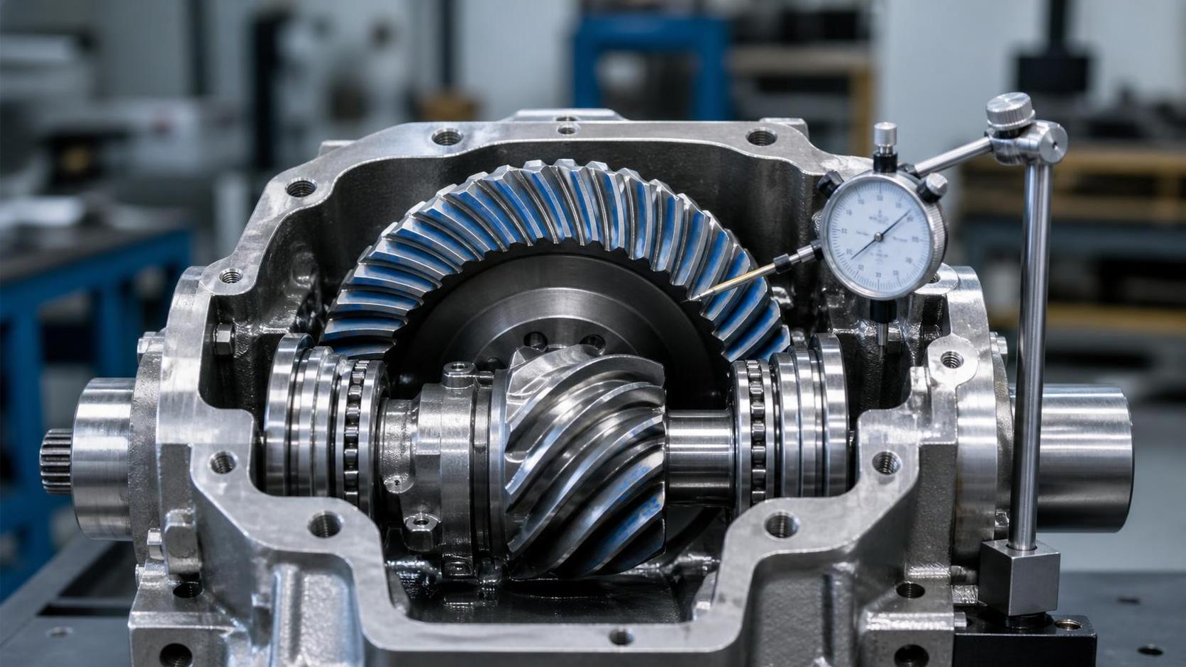
A rising whine under load, a rhythmic knock during coast-down, or metallic debris in the oil can be the first visible signs that a gearbox bevel gear set is losing its intended mesh. Once the contact pattern moves toward a tooth edge, local stress rises sharply. Wear can then progress from polishing to pitting, scuffing, tooth chipping, and, in severe cases, fractured teeth or damaged bearings. Stopping at the first symptom is usually less disruptive than replacing a complete gear train after secondary damage has spread.
Diagnosis should begin with evidence from the operating condition rather than with the removed gear alone. Bevel gears transmit torque through intersecting shafts, so tooth damage may be the result of a gear defect, but it may also originate in bearing clearance, housing distortion, incorrect shim thickness, shaft runout, inadequate lubrication, or a transient overload. Replacing only the visibly damaged member without locating the source can recreate the same failure pattern quickly.
Read the Damage Pattern Before Removing Parts
Clean the exposed teeth carefully and inspect both the drive and coast flanks. Keep the pinion and mating gear identified as a set. Their marks tell a more complete story together than either component can alone. Record the direction of rotation, load direction, lubricant condition, backlash measurement, and bearing end play before adjustments are disturbed.
Uniform bright polishing across the designed contact area may be normal running-in. A narrow, mirror-like band near the toe, heel, face, or flank is different. It indicates that the load is concentrated over too small an area. The distinction matters because a contact pattern can look acceptable at no load while shifting substantially under torque.
- Pitting: Small craters usually begin where repeated contact stress exceeds the surface fatigue capability. Initial pits may be shallow and isolated; larger pits with flaking edges indicate progressing fatigue.
- Scuffing or scoring: Smearing in the sliding direction, blue or brown discoloration, and torn surface material point to lubricant-film failure, excessive temperature, incorrect oil viscosity, or a severe contact concentration.
- Toe or heel breakage: Chipped corners often accompany an off-center pattern. A single broken area can also follow impact loading, foreign material, or incorrect assembly clearance.
- Longitudinal ridges: Repeated lines along the tooth trace can be caused by abrasive particles in the lubricant, poor filtration, contaminated assembly, or debris released after another component starts failing.
- Root cracking: Cracks near the fillet may reflect cyclic bending overload, poor root finish, a hardened layer issue, or a sudden torque event. Magnetic particle inspection may reveal cracks that are not visible after cleaning.
Abrasive wear deserves particular attention because it can make every surface look uniformly dull. Inspect the magnetic plug, filter media, drain oil, and housing corners. Ferrous fuzz is common after a short initial run-in, but flakes, chips, or a heavy granular deposit indicate active damage. Bronze-colored debris may instead point to a thrust washer, bushing, or bearing-cage issue, which can alter bevel gear position before the gear teeth show obvious failure.
Contact Pattern Is a Location Measurement
A marking compound test remains one of the most useful gearbox bevel diagnostic methods. Apply a thin, even coating to several teeth, rotate through the normal loaded direction while applying resistance, then inspect the wiped contact patch on both flanks. Excess compound creates a misleadingly broad pattern, so the coating should be thin enough that the true contact zone is visible.
On a properly matched gear pair, the pattern should sit within the tooth boundaries and remain reasonably stable between drive and coast flanks. Exact target location depends on the gear design, spiral direction, mounting arrangement, and the original engineering specification. Do not force every pattern toward the geometric center without a reference. Some designs intentionally use an offset pattern to accommodate deflection during service.
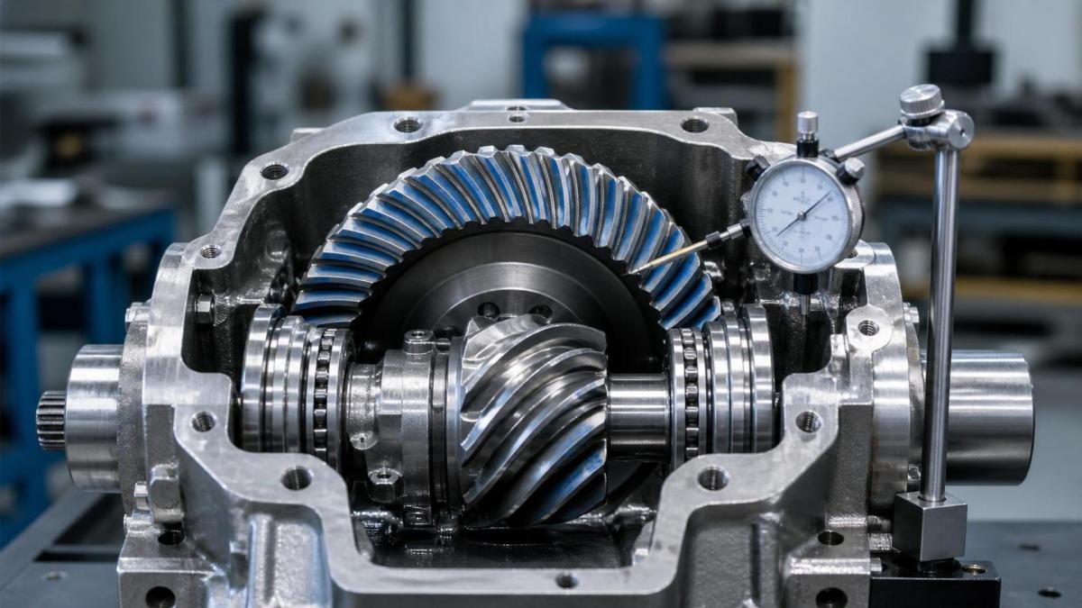
A pattern close to the tooth face or root commonly reflects a change in pinion mounting depth. A pattern driven toward the heel or toe often relates to backlash adjustment or side-to-side movement of the ring gear. These are diagnostic tendencies, not universal rules; changing one adjustment can influence both pattern location and backlash. Work from the gearbox documentation and make small, recorded changes rather than moving several shims at once.
Compare the compound result with actual backlash measured at multiple angular positions. A dial indicator positioned at the outer diameter of the driven gear can reveal variation around the circumference. Large variation may indicate gear eccentricity, debris between a bearing cup and housing shoulder, damaged mounting faces, distorted housing bores, or an incorrectly seated component. A single backlash reading cannot identify these conditions.
Separate Misalignment from Surface Fatigue
Misalignment changes where the gear teeth carry load. Surface fatigue describes what happens after localized stress is repeated over time. They often appear together, yet the corrective action differs. A replacement gear with the same alignment error will fail in a similar region, even when material quality and heat treatment are correct.
Measure shaft radial runout and axial movement close to the gear mounting location. A bent shaft, worn spline interface, damaged taper seat, or runout at a flange can cause the pitch cones to move out of relationship. Inspect keyways, retaining threads, locknuts, spacers, and the gear seating surface for burrs or fretting. A gear forced over a burred seat may appear tight while sitting slightly cocked.
Bearing condition is equally important. Tapered roller bearings, angular-contact bearings, and their preload arrangements establish the pinion and gear positions. Excess preload can generate heat and accelerate lubricant breakdown. Insufficient preload allows the shaft to move under alternating load, producing a changing contact pattern and impact at tooth entry. Brinelling, cage damage, spalling, or discolored races should be treated as a positioning problem as well as a bearing problem.
Housing inspection should not be limited to visible cracks. Measure bore size, roundness, and alignment where suitable equipment is available. Examine bearing cup seats for spinning marks and inspect joint faces for trapped sealant, coating buildup, or damage. In marine and wind-power arrangements, external structural deflection, torque-arm loading, and temperature changes can affect housing geometry. In vehicle axles and compact reducers, a distorted cover or improperly tightened fasteners may create similar changes.
Do Not Misdiagnose a Lubrication Failure
Scuffing is frequently attributed to “bad gears,” even when the gear geometry is sound. Verify oil grade, additive compatibility, fill level, breather function, and the actual operating temperature. A blocked breather can pressurize the housing and force oil away through seals, leaving the gear set underfilled. Water ingress can reduce film strength and promote corrosion pits that later become fatigue sites. Excessive foaming may prevent a stable lubricating film and make oil-level readings unreliable.
Consider how lubricant reaches the mesh. Splash systems depend on gear speed, oil level, and internal baffles. Pumped systems depend on line integrity, nozzle orientation, filter condition, and flow. During slow-speed, high-torque duty, an oil system designed around higher rotational speed may require special attention. Evidence of clean scuffing near the high-sliding portions of the teeth, combined with heat discoloration and little abrasive debris, supports a lubrication-film investigation.
A Controlled Inspection Sequence
Start with the history that can still be verified: the onset of noise, any oil change, overload event, bearing replacement, seal work, or adjustment made shortly before the symptom appeared. Then isolate the driveline where practical. Input-side defects can be mistaken for bevel gear noise because vibration travels through housings and shafts.
- Capture oil and filter evidence before draining or flushing the unit. Label samples by gearbox and operating hours if that record exists.
- Measure vibration and temperature in the same operating condition where the fault is heard. A gearbox that is quiet at idle but noisy under torque needs a loaded assessment.
- Measure backlash at several positions, then check axial and radial shaft movement. Record instrument location and direction so later measurements are comparable.
- Apply marking compound and rotate the gear set in both directions with resistance. Photograph the drive and coast patterns before altering shims or bearing settings.
- Disassemble in order, retaining shim packs, spacers, and bearing components by location. Mixed shim packs erase evidence and make restoration less reliable.
- Inspect gear teeth, bearing races, seats, seals, splines, fasteners, and housing bores. Establish whether the damage began at the mesh, support bearings, or lubricant system.
When tooth fracture has occurred, collect all accessible fragments. A missing fragment can damage adjacent teeth, bearings, oil pumps, and filters. Before fitting replacement parts, flush the housing and lines as appropriate for the lubrication system, clean magnetic surfaces, and inspect areas where debris can remain trapped. Installing new gears into a contaminated housing can score the new tooth flanks during the first rotation.
Replacement Parts Must Preserve the Gear Set Relationship
Spiral bevel and hypoid-style gear members are usually manufactured and lapped as matched pairs. Replacing a pinion with an unmatched driven gear can produce an incorrect contact pattern even if module, tooth count, and outside dimensions appear similar. Verify part identification, hand of spiral, pressure-angle family, ratio, mounting distance, face width, shaft interface, and intended rotation. A visually similar gearbox bevel component may not be interchangeable.
Material and heat-treatment requirements should match the duty. Forged alloy-steel blanks are commonly selected where high cyclic strength is required, followed by controlled machining, tooth generation, heat treatment, and final finishing appropriate to the design. Case depth, core properties, tooth finish, and dimensional control all affect fatigue resistance, but the gear cannot compensate for an unstable shaft centerline or defective bearing arrangement.
Where a gearbox contains multiple mesh types, review the full power path. A worn parallel-shaft stage can introduce debris or torsional vibration that affects the bevel stage. For related transmissions, a replacement Helical Gear should also be checked for the correct ratio, helix direction, bore fit, and backlash requirements rather than selected by nominal diameter alone.
During assembly, remove only the minimum material needed to eliminate burrs; do not polish away functional surfaces or alter hardened tooth profiles. Use calibrated measuring tools, specified tightening procedures, clean assembly lubricant, and the correct preload and backlash targets from the gearbox drawing or service documentation. After each adjustment, recheck backlash and contact pattern. Final verification should include smooth rotation through several revolutions, no tight spots, and confirmation that locking features and lubrication passages are secure.
Conditions That Create Repeat Failures
Repeat tooth wear often follows an incomplete repair. Common examples include fitting new gears while retaining a pitted bearing race, reusing crushed shims, ignoring a loose housing seat, or setting backlash at one gear position only. Another frequent issue is measuring a cold gearbox after a failure that occurs only at working temperature. Thermal expansion can change bearing preload and gear position, especially where shafts and housings use different materials or where external heat sources affect one side of the gearbox.
Handling and transport can also alter a precision gear assembly. Protect tooth flanks from impact, keep matched gears together, prevent corrosion during storage, and avoid stacking components where the teeth contact hard surfaces. Before installation after long storage, inspect preservative condition, packaging damage, and exposed machined faces. Rust staining on a tooth flank should not be dismissed if it lies within the intended contact region.
A stable repair is documented in measurements rather than assumptions: the original damage location, debris findings, bearing condition, backlash variation, contact pattern, shim changes, and final settings. This record makes later vibration or oil findings easier to interpret and prevents an adjustment history from being lost when the gearbox is opened again. Bevel gear reliability depends on the complete mesh system staying in position, supplied with clean lubricant, and operated within the load and speed conditions for which it was designed.
Please give us a message