



Related Posts
Online Message
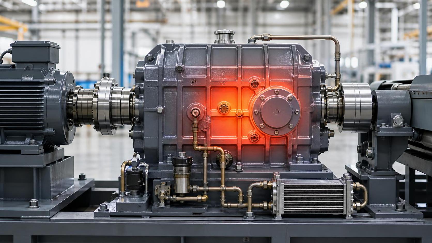
Industrial transmission overheating under variable loads usually develops when heat is generated faster than the housing, lubricant, and cooling path can remove it. A gearbox may run at an acceptable temperature during steady operation, then climb rapidly when torque changes repeatedly, starts are frequent, or the driven equipment alternates between light and heavy resistance. The temperature rise is a symptom of increased friction, churning loss, poor heat transfer, or a load condition outside the transmission's practical operating range.
Ignoring the pattern can shorten lubricant life, discolor gear teeth, damage bearing cages, harden seals, and change backlash as components expand. A single high reading does not identify the failed part. The useful question is when the temperature changes: during acceleration, at peak torque, after a direction reversal, after several hours of operation, or only when ambient temperature rises. That operating sequence often points to the source of excess heat.
Variable Torque Changes the Heat Balance
Under a constant load, gears and bearings establish a relatively stable oil film and a predictable heat level. Variable loads disturb that condition. Torque spikes increase tooth contact stress and bearing load, while repeated unloading and reloading can cause small sliding events at gear flanks, splines, couplings, and rolling elements. If the load cycle is rapid, the transmission may not have enough time to release accumulated heat before the next high-load interval.
Inertia is frequently overlooked. A conveyor, mixer, crusher, winding system, or reciprocating machine may require much higher torque while accelerating than during normal running. Sudden starts, plugging, rapid reversals, and frequent stop-start cycles transfer that demand through shafts and gear meshes. A motor may appear correctly sized when average power is considered, while the actual torque peaks impose thermal stress on the gearbox.
Load variation can also create torsional vibration. When the natural frequency of the motor, coupling, shafting, and driven machine is excited, the transmission may experience oscillating torque beyond what is visible in a basic current reading. Rattling at low speed, recurring noise during speed changes, or unusual movement at a flexible coupling can indicate a dynamic problem rather than a simple lubrication fault.
Lubricant Problems That Raise Temperature
Oil condition has a direct effect on transmission temperature because the lubricant must separate moving surfaces and carry heat away from gear teeth and bearings. An incorrect viscosity can fail in two different ways. Oil that is too thin at operating temperature may not maintain a sufficient film under peak torque. Oil that is too thick can increase churning losses, especially at high speed or cold start, and may prevent proper flow through internal passages.
Using the right viscosity grade is only part of the selection. Gear geometry, rolling bearing type, speed, load, ambient temperature, filtration arrangement, and splash or forced lubrication method affect the required formulation. Some industrial transmissions need additives suitable for heavily loaded sliding contacts, while certain bearing and bronze-containing arrangements may require confirmation that the additive package is compatible with internal materials.
Low oil level is a familiar cause, but excessive oil level can be equally damaging. When rotating gears dip too deeply into the sump, they whip air into the oil and consume power through churning. Aerated lubricant loses effective film strength and may produce foam that interferes with bearing supply. Conversely, a low level can leave upper bearings or high-speed meshes under-lubricated during load peaks.
- A milky appearance may indicate water contamination, which reduces lubricating performance and can promote corrosion inside bearings and gear teeth.
- Darkened oil with a sharp burnt odor may indicate overheating or oxidation, although color alone should not be used as a diagnosis.
- Persistent foam near the breather or sight glass can point to overfilling, air ingress on a suction line, incompatible oil, or severe churning.
- Metallic debris in a filter or magnetic plug requires comparison with prior inspection results and examination of likely wear locations before the transmission is returned to high load.
Lubricant circulation faults often appear only under variable loads. A partially blocked line may supply enough oil at low demand but become inadequate when viscosity falls or bearing losses increase. On units with pumps and coolers, verify actual flow and pressure rather than assuming that a running pump means adequate delivery. A bypass valve stuck open, a fouled cooler, a restricted filter, or a damaged pickup screen can all reduce heat removal.
Misalignment and Gear Contact Patterns
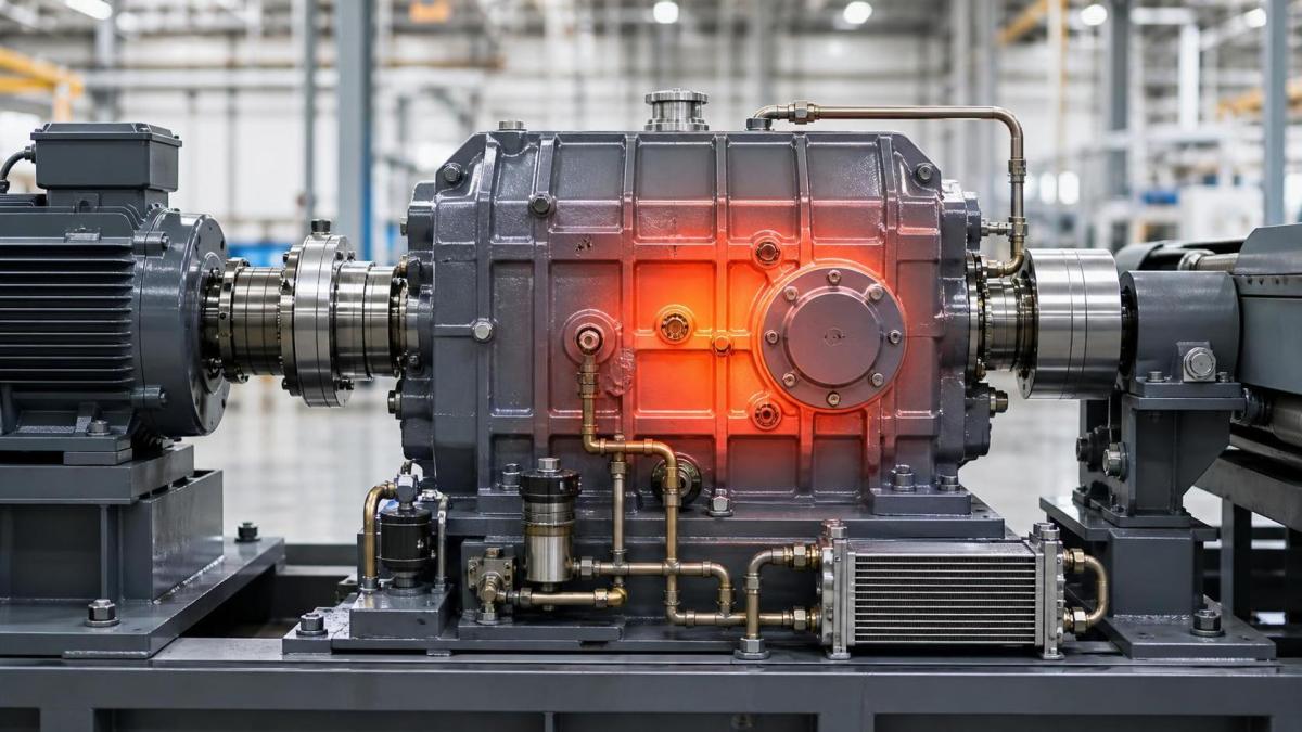
Misalignment converts useful power into heat. The source may be within the transmission or in the connected equipment. A coupling that is offset, angularly misaligned, or subject to axial forcing can overload input or output bearings. As bearing clearance changes, gear shafts can deflect and move the tooth contact toward an edge. The resulting concentrated contact raises friction and can produce localized scoring long before a general temperature alarm occurs.
Foundation movement deserves attention when overheating begins after installation, relocation, structural repair, or a change in driven load. Soft foot at the motor or gearbox feet, loose hold-down bolts, distorted baseplates, and pipe strain on adjacent equipment can change alignment during operation. Cold alignment values may be acceptable while thermal expansion moves the shafts out of position at normal load. Measurements should therefore be reviewed alongside operating temperature and actual running position where feasible.
Gear tooth contact inspection provides useful evidence. A broad, centered contact pattern generally distributes load more effectively than a narrow band at the tooth end. Polished edges, heavy wear near one face, pitting concentrated at a corner, or abnormal heat tint can support an alignment or shaft-deflection investigation. These marks should be interpreted with gear design data, because some profiles and crown modifications intentionally alter the apparent pattern.
Manufacturing quality also affects thermal behavior. Incorrect center distance, excessive runout, poor tooth finish, inappropriate backlash, or distorted gear blanks can increase mesh friction. For high-load ring-type components, the grain flow, material consistency, heat treatment response, and machining accuracy of a Forged Ring can influence dimensional stability and load distribution after assembly. Replacement parts should be verified against drawings, material requirements, hardness requirements, and mating-component tolerances rather than selected by nominal outside dimensions alone.
Bearing Damage May Be the First Heat Source
A bearing can overheat before a gearbox as a whole appears overloaded. Excessive preload, insufficient internal clearance, poor mounting practice, contamination, electrical erosion, or raceway damage increases rolling resistance. Under changing loads, a damaged bearing may heat sharply during the portion of the cycle that applies radial or axial force in a particular direction.
Listen for changes that follow load rather than speed alone. A rough sound during one direction of rotation, a cyclic vibration near the output end, or a thermal hot spot around one bearing housing can narrow the inspection. Infrared readings are useful for comparison, but the emissivity of painted, oily, polished, and oxidized surfaces differs. Confirm suspicious readings with a consistent measurement method and, where permitted, a contact sensor at a suitable housing location.
Mounting errors are common after repair. Driving a bearing through the wrong ring, forcing it onto a shaft with poor surface finish, overheating it during installation, or failing to control interference can create internal stress. A bearing that feels normal during manual rotation may still run hot after load is applied. Shaft and housing fits must be assessed against the bearing arrangement and expected temperature difference during operation.
Cooling Capacity Can Be Adequate Until Conditions Change
A transmission that operated normally in a cool workshop may overheat after enclosure, reduced airflow, accumulation of dust on fins, or a seasonal increase in ambient temperature. Cooling surfaces need a clear path for air movement. Guards, nearby equipment, stacked materials, and buildup of oil-soaked debris can all reduce convection from the housing.
Water- or oil-cooled systems add separate failure points. Confirm coolant temperature, flow direction, fouling, leaks, valve position, and cooler bypass operation. A cooler can look clean externally while internal scale or sludge limits heat transfer. When a temperature rise tracks the load cycle but the outlet oil temperature does not respond as expected, verify sensor placement and determine whether the sensor is measuring sump oil, return oil, housing surface temperature, or a localized bearing area.
Breathers are part of the thermal system as well. A clogged breather can increase internal pressure as oil warms, encouraging seal leakage and affecting lubricant movement. Replacing a breather without addressing heavy moisture exposure or dusty surroundings may only postpone the issue. The breather type, mounting location, and service interval should match the actual environment.
Separate Overload From a Measurement Error
Before opening the transmission, confirm the temperature signal. A loose thermocouple, damaged cable, incorrect controller scaling, poor contact between a sensor and housing, or a sensor placed beside an external heat source can produce misleading values. Compare the indicated temperature with a second method at the same general location, then record readings through a complete load cycle.
After confirming the measurement, collect operating data in sequence: input speed, output speed, motor current or torque indication, load condition, oil temperature, housing temperatures at several points, ambient temperature, and cooling-system status. A trend is more useful than isolated readings. If temperature rises rapidly with a particular operation, inspect the associated torque path, coupling behavior, bearing load direction, and lubrication supply during that event.
Do not assume that lower speed always reduces heat. At low speed, oil splash may be insufficient for a design that depends on gear rotation to distribute lubricant. At high speed, churning and windage losses can increase. Variable-speed drives can move a transmission into either condition, particularly when the original lubrication and cooling arrangement was intended for a narrower speed range.
Practical Inspection Sequence During a Shutdown
Start with external evidence: leakage paths, loose fasteners, blocked vents, damaged cooling lines, coupling condition, foundation movement, and oil level after the unit has been stopped according to the equipment procedure. Record the condition before cleaning or disassembly, since the location of debris and leakage may matter.
Then review lubricant samples, filter contents, and magnetic debris. A laboratory analysis can help distinguish normal wear from active gear or bearing deterioration, but samples must be taken from a representative live zone rather than from stagnant oil at the bottom of a drained sump. If the lubricant has been changed recently, confirm the fluid identity, viscosity, quantity, and whether incompatible residual oil could remain in lines, coolers, or auxiliary tanks.
During internal inspection, examine gear flanks, bearing races, cages, shaft journals, splines, seal tracks, and oil-distribution features. Look for blueing, scoring, micropitting, abnormal polishing, flaking, fretting, blocked jets, and evidence that oil has not reached an upper mesh. Measure backlash, shaft end float, and bearing-related clearances only with the applicable assembly specifications; generic values can create a new fault in a different gearbox design.
Overheating under variable loads is often a combined condition: a torque spike exposes marginal oil film, shaft deflection shifts the gear contact, and restricted cooling prevents recovery between cycles. Restoring reliable operation requires correcting the heat source and confirming the transmission at the actual speed, load pattern, and ambient condition in which the problem occurred.
Please give us a message