



Related Posts
Online Message
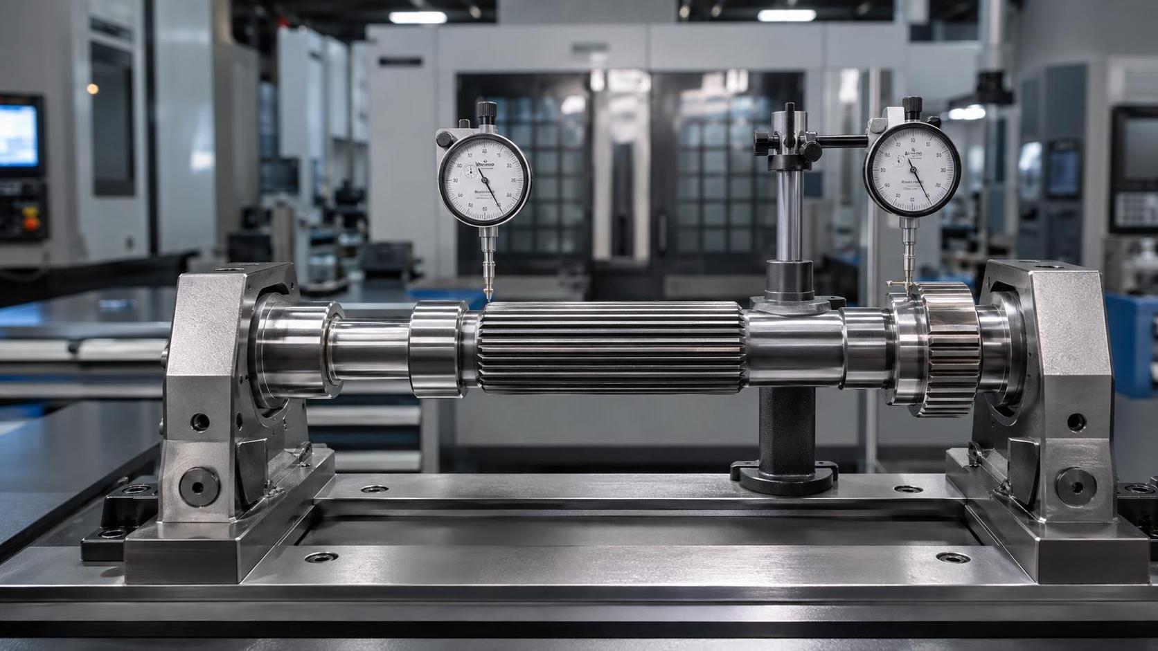
A spline shaft can meet a nominal drawing size and still create assembly noise, uneven contact, seal wear, or accelerated spline fatigue. The difference is often visible only when radial runout, tooth profile, datum strategy, and heat-treatment distortion are evaluated as one controlled system. A capable precision forged spline shafts supplier should be able to explain that system in measurable terms, not merely state that parts are inspected before shipment.
Start with the functional relationship between the shaft and its mating component. A spline that transmits high torque through a gearbox reacts differently from one used mainly for axial sliding. Automotive transmission shafts, wind-power gearbox shafts, marine driveline components, and industrial reducer shafts each place different emphasis on torsional load, cyclic reversal, lubrication, speed, corrosion exposure, and assembly repeatability. The drawing tolerance is the starting point; the application determines which deviations consume the available tolerance first.
Runout Must Be Tied to a Functional Datum
Runout is frequently discussed as a single inspection value, yet the number has little meaning without knowing what is being indicated and how the shaft is located during measurement. A spline major diameter, minor diameter, tooth flank, bearing journal, center hole, or mounting face may each produce a different reading. The functional datum should reproduce the way the shaft is supported and indexed in its assembled condition.
For example, measuring spline runout while locating a shaft on an unfinished forging surface can conceal an offset between the splines and the finished bearing journals. Conversely, a shaft may appear to have excessive radial movement when checked against a tooth tip even though the pitch diameter and flank relationship are acceptable for the intended coupling. Tooth-tip indication is useful for finding gross deformation, burrs, and damaged teeth, but it cannot independently establish spline functional accuracy.
Ask for the inspection setup used to report runout: the locating surfaces, fixture type, rotational method, indicator position, and whether the part is supported between centers, on journals, or in a dedicated gauge. A report should also distinguish total indicator reading from any calculated eccentricity value. Confusing the two leads to incorrect comparisons between suppliers.
Runout should be considered at several stages rather than only at final inspection. A part can be concentric after turning but shift after induction hardening, carburizing, quenching, straightening, or grinding. Where the shaft has multiple functional zones, the critical question is not simply whether each zone is within its isolated tolerance. It is whether the bearing seats, seal journals, gear locations, and spline pitch reference remain coaxial after all distortion-producing operations are complete.
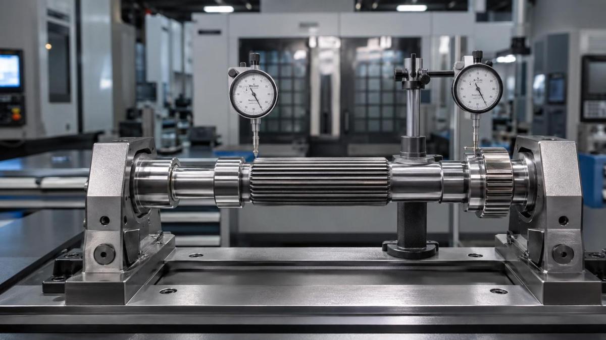
Reading Spline Profile Results Beyond Pass or Fail
Spline profile control includes more than tooth count and outside diameter. Depending on the spline form, relevant characteristics may include module or diametral pitch, pressure angle, tooth thickness, space width, effective tooth thickness, lead, involute form, pitch diameter, indexing, flank straightness, and chamfer condition. A supplier that reports only caliper measurements across the teeth is not providing enough evidence for a demanding fit.
The most useful profile evidence connects the inspection method to the functional requirement. Go and no-go gauges are efficient for production verification, especially for internal or external spline fit, but they show only whether a part falls within the gauge acceptance envelope. They do not reveal whether a trend is moving toward a limit, whether a lead error is concentrated at one end, or whether one tooth position differs from the rest. Coordinate measurement, dedicated spline measuring equipment, profile scanning, and master-part comparison each answer different questions.
Tooth thickness alone can also mislead. A shaft with acceptable tooth thickness but poor involute form may contact its mating spline near the tip or root rather than across the intended flank area. This creates high local stress even when the coupling can be assembled. Likewise, a profile result measured before surface hardening may not represent the finished component if the subsequent thermal cycle changes tooth geometry.
Separate Form Error from Indexing Error
Form error affects the shape of an individual tooth flank. Indexing error affects the angular relationship among teeth. Both may cause uneven load distribution, but they point to different process controls. Form issues are often related to die condition, finishing allowance, rolling or broaching behavior, tool wear, or grinding setup. Indexing variation can arise from fixture location, rotary positioning, tooth-forming equipment, or an incorrect reference feature.
A report that presents only a composite spline value may be adequate for a stable, low-risk application, yet it is less useful when assembly failures must be traced. For shafts used in high-load or high-cycle service, request enough detail to identify whether the deviation is repeated around the circumference, isolated to a few teeth, or increasing along the axial length. Those patterns make the production cause far easier to distinguish.
Precision Forging Changes the Evaluation Method
Precision forging offers a near-net shape route that can reduce machining allowance and preserve material more efficiently than removing large volumes from bar stock. Its value for a spline shaft depends on controlled metal flow, die design, billet preparation, trimming, cooling, and the machining sequence that follows. A forged blank with a favorable grain-flow direction can support fatigue performance, but that benefit does not eliminate the need for reliable finish control on functional spline surfaces.
The phrase “precision forged” should therefore be clarified early. It may describe a forged blank with limited machining allowance, a near-net spline form that receives light finishing, or a component whose spline remains largely as-forged. These are materially different manufacturing routes. The correct choice depends on required profile tolerance, surface finish, hardness, tooth geometry, and load path.
As-forged teeth can be suitable where the function and tolerance band allow them. When close flank contact, controlled backlash, fine surface finish, or hardened precision is required, machining, rolling, shaving, broaching, grinding, or another finishing operation may still be necessary. There is no universal hierarchy among these methods. The relevant issue is whether the selected route controls the final geometry after the last operation that can alter it.
Ask how forging datum surfaces are protected and how machining references are established. A good process route prevents the machining setup from chasing variable forged surfaces. Center holes, journal pre-machining, controlled locating diameters, or dedicated fixtures are common ways to establish repeatable reference conditions. If each operation picks up a different imperfect surface, small positional errors can accumulate until spline-to-journal runout becomes difficult to recover.
Material Consistency and Thermal Distortion
Material selection cannot be separated from geometric control. Alloy chemistry, cleanliness, billet condition, grain size, hardenability, and heat-treatment response influence both strength and distortion behavior. Two shafts made to the same nominal geometry may move differently during hardening because their section transitions, residual forging stress, machining stock distribution, and quench response are different.
Sharp changes in diameter near the spline, deep undercuts, asymmetric shoulders, and long slender shafts deserve specific discussion before production release. These features can promote uneven heating or cooling. Straightening may restore overall shaft runout while introducing localized stress or modifying the relationship between the splines and reference journals. The process record should show when straightening is performed and which dimensional characteristics are rechecked afterward.
Hardness verification is necessary but incomplete. A hardness result does not confirm effective case depth, core properties, decarburization control, or distortion after heat treatment. For a surface-hardened spline, the transition from tooth flank to root deserves attention because the root is frequently the fatigue-sensitive area. Excessive grinding after heat treatment can remove intended case depth, while inadequate finishing can leave distortion or scale that interferes with mating contact.
Production Capability Evidence That Actually Reduces Uncertainty
Capacity statements and sample photographs say little about control of a difficult shaft. More useful evidence is a process-specific package for the proposed part family. It should identify incoming-material verification, forging stages, trimming, normalization or other intermediate thermal treatment where applicable, machining references, spline forming or finishing, final heat treatment, straightening, cleaning, preservation, and final inspection.
Pay close attention to where measurements occur. If the only spline inspection is performed before hardening, the final inspection plan has a blind spot. If final runout is measured after a part is removed from the fixture that controls the functional datum, the result may not reflect assembly behavior. If a lot is accepted through sampling, the sampling logic and escalation procedure should align with the effect of a nonconforming shaft in the end assembly.
- Traceability should follow the physical part. Heat number, forging batch, heat-treatment load, machining batch, and final inspection record need a practical link to the delivered lot. Batch-level documentation is less helpful when multiple thermal loads or tool-change periods are mixed together.
- Gauge control needs scope. A calibrated indicator does not validate a worn spline plug gauge, an incorrectly aligned fixture, or a master part with unclear status. Ask how spline gauges, checking fixtures, and reference artifacts are verified.
- Reaction plans matter when results drift. A supplier should be able to state what happens when runout trends toward a limit: additional sorting, fixture verification, tool adjustment, containment of affected lots, or review of heat-treatment parameters. “Final inspection” is not a reaction plan.
Compare Quotations on the Same Technical Basis
Quotation differences often originate in assumptions that are absent from the drawing. One source may price an as-forged spline with limited dimensional verification, while another includes finish machining, heat-treatment control, dedicated gauging, and runout inspection from functional journals. Those offers cannot be compared simply by unit price or stated lead time.
Clarify the supplied condition: forged blank, rough-machined shaft, finished spline shaft, or heat-treated final component. Define which party owns mating-part validation, surface treatment, deburring, preservation, and packaging. Long spline shafts can be bent or nicked during transport if they are allowed to contact one another in bulk packaging. A part that passed final inspection may arrive with raised edges at the lead chamfer or damaged tooth corners, both of which can distort assembly feedback.
First-article approval should use the final manufacturing route, final material condition, and final inspection datum scheme. A sample produced with temporary tooling or an alternate heat-treatment path can prove basic manufacturability but may not prove repeatable production control. For assemblies with tight spline engagement, evaluate a representative mating component or approved master gauge alongside dimensional reports. Functional engagement exposes conditions that isolated measurements can miss, including burr interference, entry-chamfer mismatch, localized tight spots, and incorrect backlash.
Questions That Expose Process Depth
Rather than asking for a general quality statement, use questions that require a specific technical answer. Which surfaces locate the shaft during final spline runout inspection? Is runout verified after the final heat-treatment and straightening stages? What characteristic defines spline acceptance: tooth thickness, effective space width, profile, lead, composite variation, or a defined combination? How are forging and machining datums linked? Which features are rechecked after straightening or finish grinding?
The response should remain consistent with the drawing and the proposed process route. A vague answer may reflect an incomplete request package, but it can also reveal that inspection is being adapted after production rather than designed before tooling is released. Resolve those gaps before committing to tooling, qualification quantities, or an extended release schedule.
For demanding shaft applications, the strongest selection basis is a supplier’s ability to preserve one coherent geometric reference from forging through finished inspection. Stable runout and controlled spline profile are the visible outputs of that discipline. They are established through datum planning, controlled finishing allowance, material and thermal consistency, capable gauges, and records that make deviations traceable when they occur.
Please give us a message