



Related Posts
Online Message
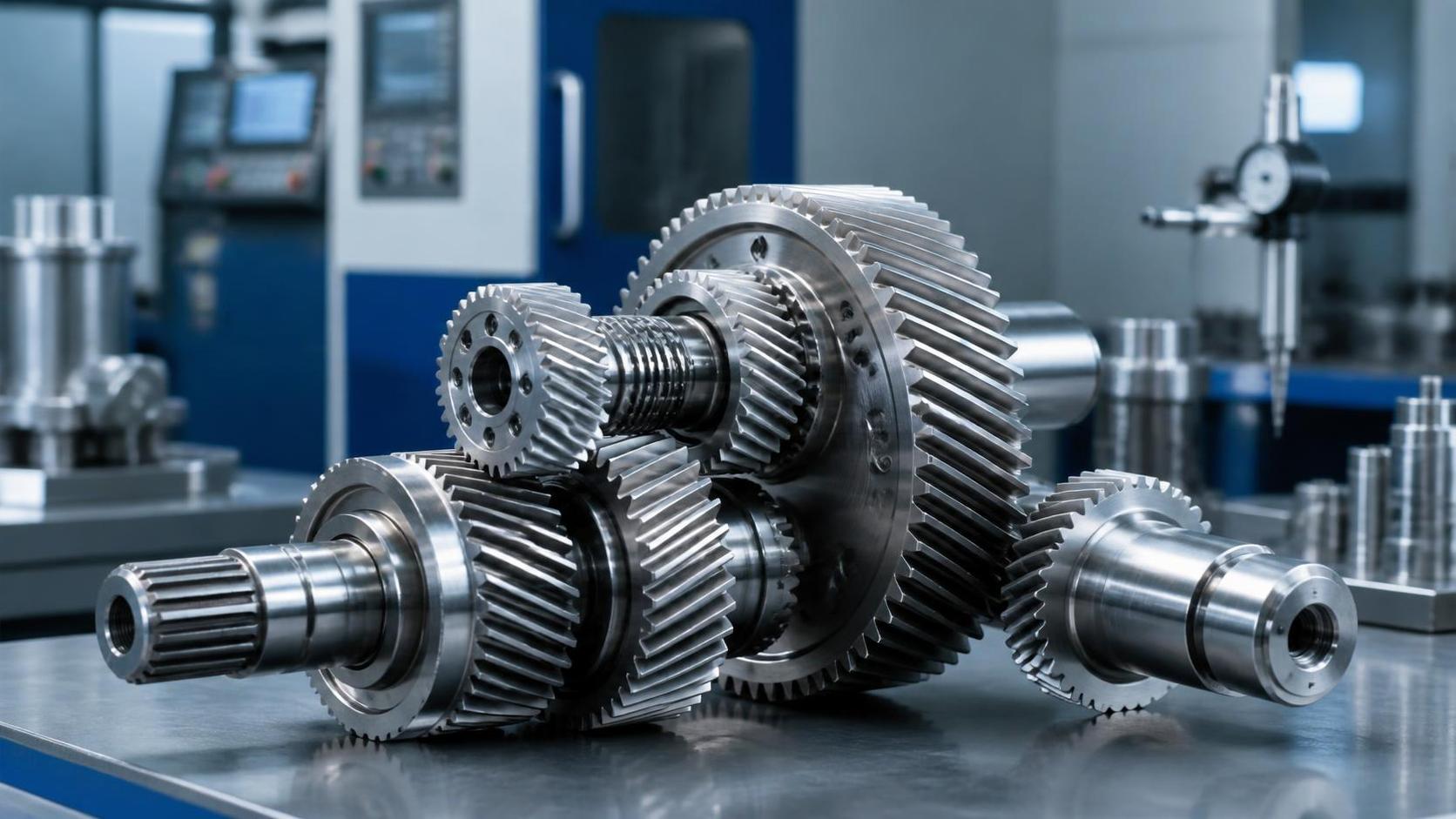
Custom Gears for Nonstandard Machines: Turning Operating Data into Specifications
When a nonstandard machine is designed around an unusual process, the transmission system is rarely a simple catalogue selection. A compact automated handling unit may have limited center distance. A marine mechanism may reverse under shock loading. A wind-related drive may experience long periods of fluctuating torque rather than a steady industrial duty cycle. In these situations, a gear that appears adequate on paper can still become the source of noise, overheating, tooth damage, unstable positioning, or an avoidable redesign late in the project.
Custom gears are not merely standard gears made to a different diameter. They are engineered components whose geometry, material route, heat treatment, accuracy level, and mating conditions are determined from actual operating data. For project managers, that distinction matters. The right early questions can prevent a transmission problem from spreading into procurement delays, test failures, spare-parts uncertainty, and changes to the machine enclosure or motor selection.
The practical goal is straightforward: convert how the machine truly works into a specification that a gear manufacturer can assess, produce, inspect, and repeat. The difficulty lies in avoiding assumptions between those steps.
Why “Required Torque” Is Not a Complete Gear Requirement
Torque is an essential starting point, but it does not tell the full story. A gearbox driving a conveyor at constant speed places a very different demand on its gears than an indexing table that accelerates, stops, dwells, and reverses several times per minute. Two machines can show the same nominal torque while imposing substantially different peak tooth loads and fatigue exposure.
A useful custom-gear brief should separate continuous torque, short-duration peak torque, start-up conditions, emergency stops, and reverse loading. It should also identify where the torque value comes from: motor rating, calculated process load, measured operating data, or an estimate based on a previous machine. If the source is uncertain, it is better to state that uncertainty than to turn an assumption into a fixed design input.
Speed deserves the same attention. Rotational speed influences pitch-line velocity, lubrication behavior, vibration sensitivity, heat generation, and the practical need for tighter tooth quality. A slow, heavily loaded reduction stage may be controlled by tooth-root strength and surface durability. A faster stage may require much closer attention to tooth profile, lead accuracy, gear balance, housing stiffness, and the interaction between gear mesh and bearing arrangement.
Duty cycle is frequently underestimated because it looks less tangible than torque. Yet the number of cycles, loaded hours per day, dwell periods, and expected service life determine how a designer should view fatigue. A mechanism that runs briefly only during batch changeovers is not equivalent to one that runs through multiple shifts. The same gear geometry may be technically possible in both cases, but the acceptable risk margin, heat-treatment choice, and validation plan may differ.
The Operating Data That Changes the Gear Design
The best custom gear projects begin with a machine-level view rather than a tooth-count request. A gear designer needs enough information to understand the complete force path: motor, coupling, shaft, bearings, gear pair, housing, driven load, and control behavior. Missing one link in that chain can make a correct gear drawing perform poorly in the finished machine.
The following inputs usually have direct consequences for the specification:
- Input and output speed ranges, not only nominal RPM.
- Continuous, peak, overload, and reversal torque.
- Required ratio, allowable ratio error, and any positioning or synchronization requirement.
- Available center distance, maximum outside diameter, face-width limit, and shaft arrangement.
- Load direction, shock events, vibration, operating temperature, contamination, and corrosion exposure.
- Lubrication method, oil type where defined, access for maintenance, and target inspection interval.
- Mating-part details, including spline, bore, keyway, shaft tolerances, bearing locations, and housing stiffness.
For a project manager, gathering these inputs early is not administrative overhead. It shortens the loop between machine design and manufacturing review. It also makes it easier to distinguish a true gear problem from a shaft-deflection, bearing-preload, lubrication, or assembly-alignment problem.
From Machine Constraints to Gear Geometry
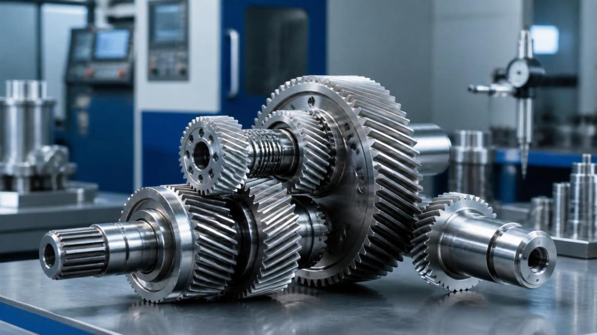
Once the operating envelope is clear, gear geometry becomes a controlled set of trade-offs. Spur gears can be appropriate where the arrangement is simple and axial thrust should be avoided. Helical gears typically provide smoother engagement, but their helix angle introduces axial load that the bearings and housing must accommodate. Bevel and spiral bevel gears are used where power changes direction, while planetary arrangements are often considered when high reduction is needed in limited space.
The choice is never based on geometry alone. Module or diametral pitch, pressure angle, tooth number, face width, profile shift, helix angle, and backlash all interact. Increasing face width can improve load distribution only if the shafts, bearings, and housing keep the gears sufficiently aligned. Reducing size may satisfy a compact layout but leave less margin for heat dissipation or tooth strength. Using a larger module can improve robustness, while a finer tooth form may be necessary to obtain a ratio within a limited center distance.
Backlash deserves particular care in nonstandard equipment. Too little backlash can lead to tight mesh when thermal expansion, housing distortion, coating thickness, or assembly variation enters the system. Too much can reduce positioning consistency and create impact during reversal. There is no universal “best” backlash value; it must be related to temperature range, gear type, manufacturing capability, assembly method, and the machine’s functional tolerance.
Tooth contact pattern is equally important. A gear pair may meet dimensional requirements while carrying load unevenly across the tooth face because of misalignment. This is why a request for custom gears should include the mating gear condition and, where possible, relevant information about shaft span, bearing type, and housing construction. In complex units, the gear should not be treated as an isolated purchased part.
Material and Heat Treatment Must Follow the Failure Risk
Material selection is often discussed in broad terms—strength, hardness, wear resistance—but the real decision should relate to the failure modes the machine cannot tolerate. Tooth-root fatigue, surface pitting, scuffing, abrasive wear, plastic deformation, and corrosion do not have identical causes or identical solutions.
A carburized and hardened gear can provide a hard working surface with a tougher core, making it suitable for many demanding transmission applications. Induction hardening may be considered for certain shapes, sizes, or production needs. Through-hardening can remain practical where loading, geometry, and service requirements allow it. The appropriate route depends on the steel grade, tooth dimensions, required distortion control, machining sequence, and inspection requirements. It should not be selected solely because it is familiar or because a previous gear used that process.
Heat treatment also affects the production plan. Distortion after hardening may require finishing operations, and the amount of machining allowance must be established before forging or rough machining begins. If a gear is integrated with a shaft or spline, the sequence becomes even more consequential: where to machine before treatment, what surfaces need final finishing afterward, and how to protect reference features.
This is one reason why precision forging can be valuable for selected gear and shaft components. Near-net-shape forging may reduce material removal and establish a more efficient manufacturing route when the part geometry and volume justify it. It is not a universal substitute for machining, but it can reduce unnecessary turning and material loss in an appropriately engineered process.
Manufacturing Tolerances Are Functional Decisions
An overly broad tolerance can create noise, variable backlash, and poor load distribution. An unnecessarily tight tolerance can increase cost, extend lead time, and make inspection difficult without adding functional value. The job is to define the tolerances that protect the machine’s performance, not to apply the smallest possible number everywhere.
For gears, the specification may need to address tooth profile and lead deviation, pitch accuracy, runout, bore or spline accuracy, tooth flank finish, and the datum relationship between the gear and its mounting features. For a gear-and-shaft assembly, concentricity and perpendicularity can be as influential as the tooth geometry itself. The same principle applies to a connected Drive Shaft: its interfaces, straightness, and bearing-seat relationship should be considered alongside the gear mesh rather than after the gear is released for production.
Inspection planning should be discussed before production, especially when the design includes modified tooth forms, nonstandard splines, bevel geometry, or integrated forged features. The manufacturer and project team need a shared understanding of what will be checked, against which drawing references, at what stage, and what documentation is needed for acceptance. This is much more useful than discovering after delivery that a critical functional feature was not identified as a measured characteristic.
Prototype Decisions That Protect the Project Schedule
Nonstandard machine projects often lose time when prototype parts are ordered before the design assumptions are stable. A prototype should answer specific questions: Does the ratio behave as intended? Is the temperature acceptable under representative loading? Does the contact pattern remain stable? Is backlash suitable after assembly? Does the machine produce objectionable vibration or noise? Can the part be manufactured repeatedly with the intended process?
These are not all the same test. A dimensional inspection can confirm whether a part follows the drawing. It cannot by itself confirm that the housing remains aligned under load or that lubrication reaches the mesh at speed. Conversely, an assembled machine test may reveal a problem without immediately identifying whether its origin is gear geometry, shaft deflection, bearing arrangement, motor control, or assembly tolerance stack-up.
For this reason, a staged review is often more efficient than treating prototype and production as a single purchase decision. Start with the available operating data and layout. Review the proposed gear form and manufacturing route. Confirm critical drawing features and inspection points. Then use prototype findings to decide what genuinely needs revision before tooling, batch production, or release to the wider machine build.
Common Specification Gaps That Create Avoidable Risk
One common gap is supplying only an old sample without explaining the new machine conditions. A sample can reveal general geometry, but it may not show actual material condition, heat-treatment depth, tolerance intent, load history, or the original designer’s compromises. Reverse engineering is useful, yet it should be combined with current operating requirements rather than treated as a complete design authority.
Another gap is specifying a gear but omitting the mating component. A pinion and wheel are a mesh, not two independent items. If one component is changed, the pair should be reviewed together. This becomes especially important when replacing worn gears in equipment where the original mating part remains in service.
There is also a tendency to request the material first and discuss the process later. In practice, forging feasibility, machining references, heat treatment, tooth finishing, and final inspection are connected. Early manufacturing input can expose impractical corner radii, insufficient allowance, inaccessible features, or tolerance combinations that make a part harder to produce consistently.
Building a More Reliable Custom Gear Supply Path
A capable supplier should be able to connect design discussion with production reality. Liaocheng Jiucheng Auto Parts Co., Ltd., established in 2015, combines R&D, production, and sales activities around precision forgings and machined transmission components. Its work includes automotive gears, wind power gearbox parts, mechanical and marine gear parts, as well as bevel gears, spiral gears, reducer gears, planetary gears, transmission shafts, and spline shafts.
The company operates an 8,000-square-metre factory, including precision forging and mechanical processing workshops. Its team includes engineering and dedicated quality personnel, a structure that supports the necessary conversation between part geometry, process route, and inspection. For project teams, the useful point is not the facility description alone; it is the ability to examine whether a forged blank, machined gear, heat-treatment sequence, and final verification method are aligned with the functional requirement.
Jiucheng’s emphasis on precision forging and reduced machining reflects a practical manufacturing question: can the component meet its functional need while using material and energy more efficiently? The answer depends on part design and production conditions, but bringing that question into the early review can help prevent a costly process from becoming the default simply because it was used on an earlier design.
Before releasing custom gears for a nonstandard machine, confirm the actual load spectrum, speed range, ratio, installation envelope, lubrication approach, mating-part interfaces, and acceptance criteria. Those details turn a gear drawing into a working transmission specification—and give the project a much better basis for moving from prototype validation to repeatable production.
Please give us a message