



Related Posts
Online Message
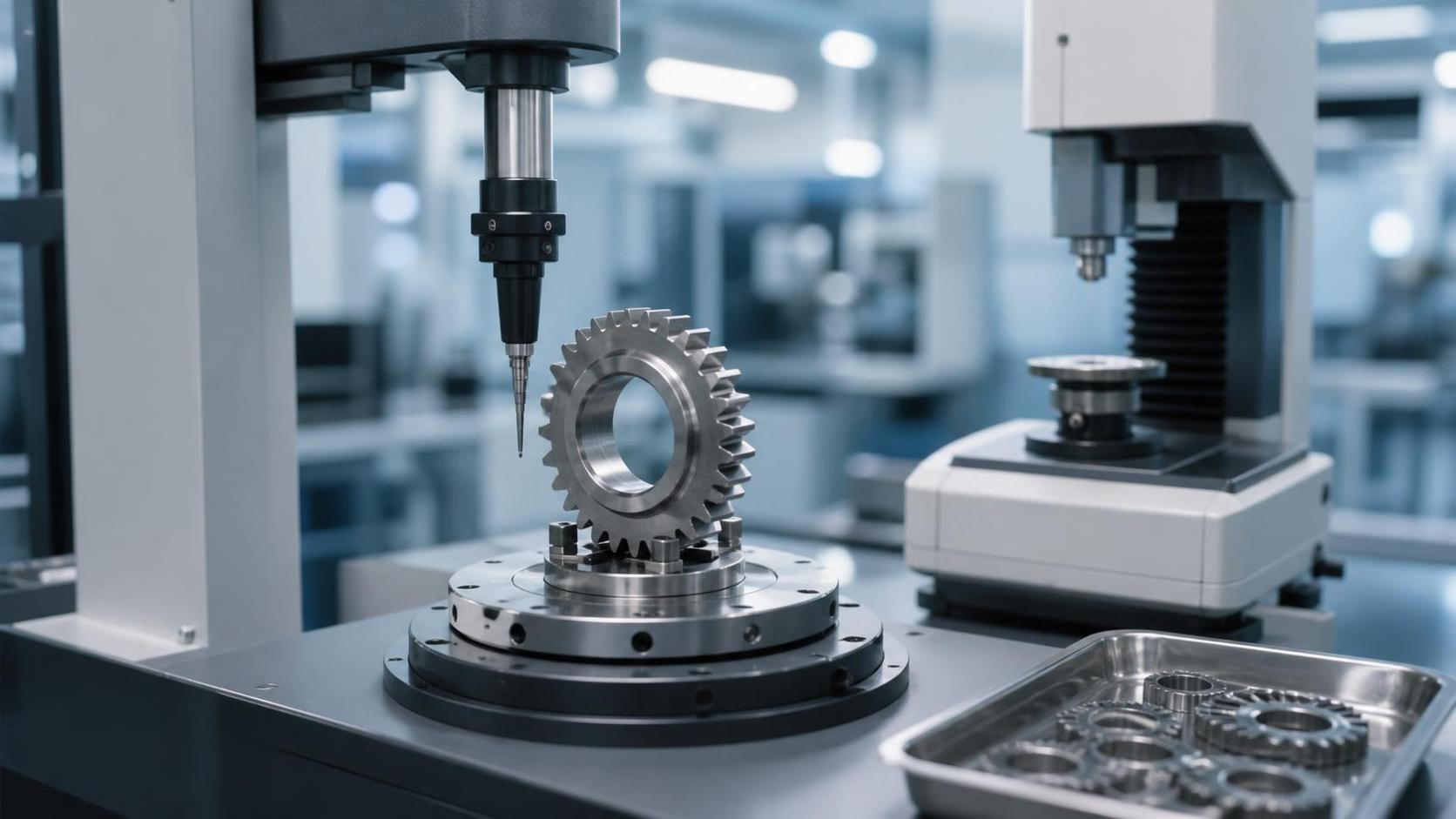
Factory Gear Quality Control: Key Tests Before Parts Leave the Production Line
A gear can look flawless on a packing bench and still fail early in service. The most expensive defects are often not obvious: a shallow case depth, a tooth profile drift that only appears under load, a machining burr left in an oil passage, or a hardness pattern that creates a brittle tooth root. In automotive drivetrains, wind power gearboxes, marine transmissions, and industrial reducers, these issues may lead to noise, heat, vibration, tooth pitting, or sudden loss of torque transmission.
That is why factory gear quality control cannot be limited to a final visual inspection. It has to follow the manufacturing route—from incoming steel and precision forging through machining, heat treatment, finishing, cleaning, and release. For quality and safety teams, the practical question is not simply whether a part meets a drawing at one moment. It is whether the evidence shows that the process repeatedly produces parts capable of surviving their intended duty cycle.
The exact inspection plan depends on the gear type, material, heat-treatment route, load spectrum, and customer specification. A small spur gear for a compact mechanical assembly does not carry the same risk profile as a gearbox gear used in a heavy vehicle or wind turbine. Still, the core controls are broadly similar, and weaknesses in any one of them can undermine the rest.
Quality starts before forging, not after machining
Incoming material verification is the first gate. Gear performance begins with the steel grade, chemical composition, cleanliness, and condition of the billet or bar. A material certificate may be necessary, but it should not be treated as the only control. Depending on the customer’s requirements and risk level, factories may use positive material identification, chemistry checks, or metallographic review to confirm that the received material matches the approved grade and heat number.
Traceability matters here because a later hardness or fatigue concern cannot be investigated properly if the part cannot be connected to its original material batch. Good practice is to preserve the link between material heat, forging lot, machining route, heat-treatment batch, and final inspection record. This is particularly important when several gear sizes or variants share equipment and operators.
Precision forging introduces another layer of risk. The process can reduce material waste and downstream turning, but it also makes die condition, billet temperature, forming force, and cooling discipline central quality variables. A forged blank may be close to net shape while still carrying laps, folds, underfill, excessive flash, die mismatch, or unfavorable grain flow. These defects should be identified before expensive machining is added.
At Liaocheng Jiucheng Auto Parts Co., Ltd., precision forging and mechanical processing are operated within the same production environment. That kind of arrangement can make process handoffs easier to control, provided that each handoff has a clear acceptance standard. A blank should not move forward merely because it can be machined; it should move forward because its forging condition is suitable for the required mechanical and tooth-quality outcome.
Forging and blank inspection: finding defects while they are still cheap
The inspection of a forged gear blank normally combines visual review, dimensional checks, and, where required, non-destructive testing. Visual inspection looks for cracks, folds, scale-related damage, sharp flash remnants, and surface discontinuities. It is basic work, but it should be done under adequate light and with clear defect examples available to inspectors. “Acceptable appearance” is too vague for production control.
Key blank dimensions include bore stock, face-width allowance, hub geometry, outside diameter, concentricity references, and machining datum condition. If the datum surface is distorted, subsequent gear cutting can be accurate relative to the wrong reference. That is one reason a dimensional check at the blank stage is not redundant with final inspection.
Magnetic particle inspection is often considered for ferromagnetic components when surface or near-surface cracking is a concern. Ultrasonic inspection may be relevant for larger sections or components with a higher risk of internal discontinuities. Neither method should be added as a ceremonial checkbox: the inspection method, sensitivity, acceptance criteria, and sampling scope need to match the part’s risk and the applicable customer or product standard.
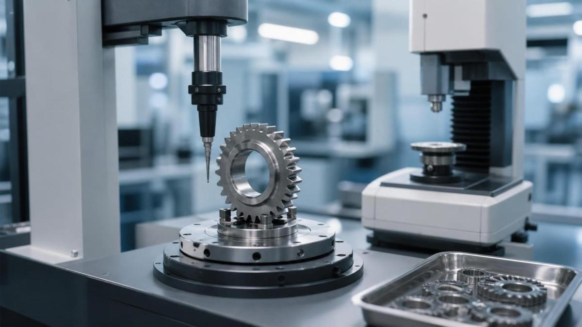
Machined geometry: tooth measurement is only part of the picture
After gear cutting, shaping, hobbing, milling, grinding, or honing, a factory gear must be assessed as a functional geometry rather than a collection of isolated dimensions. Tooth count, module or diametral pitch, pressure angle, helix angle where applicable, face width, bore size, and keyway or spline features all need confirmation against the drawing.
However, the most consequential checks usually go further. Lead deviation, profile deviation, pitch variation, radial runout, total composite error, and tooth-thickness measurements can reveal whether the gear will rotate smoothly and distribute load as intended. The relevant tolerances should come from the customer drawing or an agreed gear-quality system, such as the ISO or AGMA framework specified for the project. A general-purpose factory limit should never override a tighter customer requirement.
Runout deserves particular attention. A gear with an accurate tooth profile but poor concentricity to its bore or mounting datum can produce cyclic mesh variation. In service, this may be perceived as noise or vibration; in a high-load reducer, it can contribute to uneven tooth loading. Inspectors should therefore understand which datum establishes functional rotation. Measuring a gear on an easy-to-grip surface instead of the true assembly reference can give a misleading result.
For a Spur gear, tooth contact is especially useful as a practical functional check. A controlled rolling or meshing test with a suitable master gear can expose pitch errors, eccentricity, burrs, and rough tooth surfaces that may not be obvious in a dimensional report. It does not replace analytical profile measurement where that is required, but it gives a valuable reality check: does the part mesh consistently, quietly, and without tight spots?
Heat treatment: the stage where a compliant drawing can still become a bad gear
Heat treatment changes the gear’s performance envelope. Carburizing, carbonitriding, induction hardening, through hardening, nitriding, and other routes produce different hardness distributions, case characteristics, distortion behavior, and fatigue properties. The required method is application-specific. It should be selected and validated against the design requirement, not chosen only for short-cycle production.
Typical verification may include surface hardness, core hardness, effective case depth where applicable, microstructure examination, and distortion measurement after heat treatment. The test location is important. Measuring hardness on a non-critical surface can produce a number that looks acceptable while revealing little about the tooth flank or root condition. Likewise, case-depth assessment needs an agreed method and definition; different specifications may refer to different hardness thresholds or measurement practices.
Distortion is a recurring practical issue. A gear may pass pre-heat-treatment geometry checks but shift after quenching or carburizing. That is why final tooth measurement must be performed at the correct point in the routing—after the processes that can change geometry, and after any grinding or honing used to correct it. Releasing a gear based on pre-heat-treatment dimensions is a surprisingly common documentation mistake.
Quality teams should also watch for decarburization, grinding burn, quench cracking, and excessive retained austenite when the product specification or process risk calls for such control. These conditions are not always visible to the naked eye. A polished gear can still contain metallurgical conditions that shorten its useful life.
Final inspection should confirm function, condition, and identity
Final release is where the evidence comes together. The inspector should confirm that the correct part number, revision, material route, heat-treatment status, and traceability marking are present. A perfectly measured component shipped under the wrong revision or mixed with a similar variant is still a quality failure.
The final visual check should be deliberate rather than rushed. Look for handling damage, corrosion, dents on tooth flanks, residual burrs, thread damage, incomplete cleaning, and protective-coating problems. On gears used in lubricated assemblies, cleanliness is not cosmetic. Loose chips or abrasive residue may circulate with oil and damage bearings, seals, and mating gears.
For critical gears, the release file commonly needs more than a pass/fail stamp. It may include first-piece approval, in-process records, final dimensional results, hardness records, non-destructive test results where required, calibration status of measuring equipment, and a nonconformance disposition if any deviation occurred. The record should allow a customer or internal investigator to understand what was measured, by whom, on which batch, and against which acceptance criterion.
Sampling plans are useful, but they do not remove process responsibility
Not every characteristic needs to be measured on every piece, but the decision must be risk-based. Safety-critical features, characteristics prone to drift, and dimensions with poor downstream detectability often justify tighter control. A stable process with demonstrated capability may support rational sampling for some routine dimensions. A new tool, changed heat-treatment load, material-lot change, or abnormal machine event should trigger more intensive inspection.
One weak approach is to inspect only finished parts and assume sorting will protect the customer. Sorting can contain a problem temporarily, but it does not explain why the process shifted. Effective control uses inspection results to act on the cause: worn hobs, fixture movement, furnace loading differences, incorrect quench conditions, inadequate coolant filtration, or unclear operator instructions.
This is especially relevant in mixed production environments handling gears, bevel gears, planetary components, reducer gears, transmission shafts, and spline shafts. Similar-looking parts can have different inspection priorities. The control plan should reflect the actual functional risk of each part family rather than applying one generic checklist across the workshop.
What safety and quality managers should challenge before release
A release decision is stronger when the team can answer a few direct questions. Was the part measured after its final geometry-changing operation? Were the correct functional datums used? Is heat-treatment verification linked to the same batch as the parts being released? Are gauges calibrated and suitable for the tolerance being checked? Has a process change occurred since the last approved run? And if a defect was found, is the containment limited to sorting, or has the root cause been addressed?
The best factory gear inspection systems do not depend on one final inspector catching everything. They build controls at the points where defects are created, preserve traceability when decisions are made, and treat unusual measurement trends as an early warning rather than an inconvenience. Before a gear leaves the line, the goal is not merely to prove that it can be shipped. It is to have credible evidence that it will mesh, carry load, and remain safe in the machine it was built for.
Please give us a message