



Related Posts
Online Message
How Bevel Gear Manufacturers Control Contact Patterns and Backlash
For technical evaluators, contact pattern accuracy and backlash control are decisive factors in bevel gear performance, noise, load capacity, and service life. Leading bevel gear manufacturers combine precision forging, controlled machining, gear inspection, and assembly verification to achieve reliable meshing under demanding operating conditions. This article explains the key manufacturing controls behind stable tooth contact and consistent backlash.
The difficulty is easy to underestimate. A bevel gear pair does not simply transmit motion between intersecting shafts; it carries load through a moving contact zone across a curved or tapered tooth surface. Small changes in mounting distance, shaft angle, runout, heat-treatment distortion, or tooth geometry can move that zone toward the toe, heel, face, or flank of the tooth. The gear may still rotate, yet noise, local stress, scuffing risk, and fatigue life can change materially.
That is why a drawing that specifies only module, tooth count, pressure angle, and material is rarely enough for a critical spiral bevel or straight bevel application. The required performance depends on the complete system: pinion and gear geometry, housing stiffness, bearings, shaft positioning, lubrication, operating torque, speed, and temperature range. A capable supplier has to understand where the component will live before deciding how tightly individual dimensions should be controlled.
Contact Pattern Is a Functional Result, Not Just an Inspection Mark
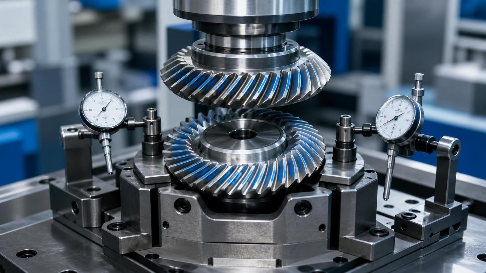
A contact pattern is the visible indication of where mating teeth touch under light load. It is commonly checked by applying marking compound to one member, rolling the pair through mesh, and observing the transferred pattern. This check is useful, but it should not be treated as a stand-alone acceptance criterion. Pattern location, length, and shape must be interpreted against the design intent and the mounting condition used during testing.
For many bevel gear sets, the desired pattern sits away from the tooth edges. Edge contact can concentrate load and leave little margin for deflection, thermal growth, or assembly variation. However, there is no universal “perfect” pattern that applies to every design. A pattern optimized for a lightly loaded marking check may shift under torque. Likewise, a gear intended for a rigid automotive axle may need a different contact adjustment philosophy from one used in a wind gearbox, marine drive, or industrial reducer.
The manufacturer therefore begins with the generated tooth geometry and the specified mounting data. In spiral bevel production, parameters such as spiral angle, pitch cone geometry, face width, crowning, profile modification, and tooth depth affect how the pair carries load. In straight bevel gears, the geometry is less complex in appearance but remains sensitive to cone distance and axial positioning. Tooth contact cannot be controlled reliably if these geometric relationships are disconnected from the final assembly condition.
Backlash Must Be Controlled as a System Variable
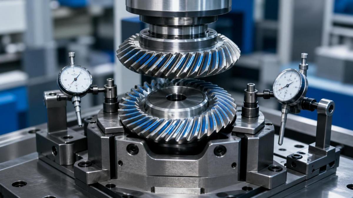
Backlash is the clearance between non-contacting tooth flanks when the mating pair is held at a defined position. It permits lubricant entry, accommodates manufacturing and assembly variation, and helps prevent tooth interference as temperatures change. Too little backlash can produce tight mesh, elevated friction, heat, noise, and accelerated wear. Too much can create impact during torque reversal, objectionable noise, and reduced positional accuracy.
The common mistake is to view backlash as a number belonging to the gear alone. In practice, assembled backlash is influenced by tooth thickness, pinion and gear mounting distances, bearing preload, housing machining, shaft end play, radial runout, and the way the gear set is installed. A gear pair can meet tooth-thickness requirements individually and still show unacceptable backlash after assembly if the housing datum structure is inconsistent.
For this reason, technical specifications should clearly state where and how backlash is to be measured. A meaningful requirement identifies the mounting condition, measuring location, inspection torque or direction where relevant, and temperature assumption. It should also distinguish between rotational backlash measured at a stated radius and normal backlash considered at the tooth flank. These are related, but they are not interchangeable without the relevant geometry.
The Manufacturing Controls That Matter Most
Bevel gear manufacturers typically control contact behavior through a chain of operations rather than one final adjustment. The first control point is the blank. Forging quality affects grain flow, material continuity, machining allowance, and the stability of later operations. A poorly controlled blank can introduce eccentricity or uneven stock that makes accurate tooth generation more difficult.
Precision forging can be particularly valuable when it produces a near-net blank with consistent reference surfaces and reduced machining removal. It does not eliminate the need for careful tooth machining or inspection, but it can improve process stability. Liaocheng Jiucheng Auto Parts Co., Ltd., established in 2015, combines a precision forging workshop with mechanical processing capability for automotive, wind power, mechanical, and marine gear components. This type of integrated route is relevant because the relationship between forging datums and subsequent machining datums must be maintained, not assumed.
Machining setup is the next critical layer. Face runout, bore position, locating shoulder accuracy, and mounting-face perpendicularity all influence how the gear sits in the assembly. On a bevel gear, these errors can shift the effective mounting distance and alter contact more dramatically than an evaluator might expect from a conventional dimensional report. Manufacturers should use datum strategies that reflect the customer’s actual assembly references rather than relying only on convenient chucking surfaces.
Tooth cutting, milling, grinding, lapping, or other finishing processes then establish the functional flanks. The selected route depends on gear type, required accuracy, material condition, volume, noise expectations, and whether the gear is supplied as a matched pair. Lapping can improve smoothness and conformity within a set, but it also creates pairing dependence. If gears are lapped as matched sets, traceability and pairing identification should be retained through packing and assembly. Interchanging one member with a visually similar gear can disturb the established contact condition.
Heat Treatment and Distortion Planning
Heat treatment deserves explicit attention in any evaluation of gear mesh control. Case hardening, through hardening, nitriding, or other treatments can change bore size, tooth thickness, runout, and flank form. The amount and direction of movement depend on material, blank geometry, prior stress condition, fixturing, furnace practice, and quench method. There is no responsible way to promise a universal distortion value without reviewing the part and process.
A practical supplier plans for this movement through machining allowances, controlled heat-treatment routes, and post-treatment verification. Where the application demands it, tooth finishing after heat treatment may be necessary. Where it does not, process capability still needs to be demonstrated through inspection records and representative production control. Technical evaluators should ask whether the reported tooth measurements are taken before or after heat treatment; that distinction often explains otherwise confusing results.
Inspection Should Connect Geometry to Assembly Performance
Dimensional inspection remains essential, but bevel gear acceptance should not stop with a general diameter check or a visual review of teeth. Depending on the gear design and agreed requirement, meaningful inspection may include tooth thickness, pitch-related characteristics, profile and lead deviation, tooth runout, bore and face runout, mounting distance, surface condition, and hardness or metallurgical checks where applicable. The selected controls should correspond to the risk of the application, not merely to the instruments available on the shop floor.
Pair testing is where individual measurements become functional evidence. A dedicated rolling or assembly fixture can reproduce the specified shaft angle, center relationship, and mounting distance. The pair can then be checked for backlash, contact pattern, rotation smoothness, and sometimes transmission error or noise, if these are part of the agreed validation plan. The fixture itself must be controlled. A highly accurate gear cannot be fairly evaluated on a fixture with uncertain spindle runout or unstable axial location.
Relevant standards may be specified by the customer or selected according to the market and application. ISO and AGMA documents are frequently referenced in gear work, but the applicable edition, gear category, accuracy designation, measurement method, and contractual requirement must be confirmed for the specific project. A standard reference alone does not define every functional requirement for a bevel gear assembly.
Reading Contact Pattern Errors During Evaluation
A pattern near the toe or heel often points to a mounting-distance issue, while movement toward the face or flank can indicate a change in shaft angle, tooth depth relationship, or other setup condition. These tendencies are useful diagnostic clues, not a substitute for design data. Spiral bevel geometry is especially sensitive, and one observed pattern can have more than one cause.
The right response is not to adjust blindly until the marking looks centered. Evaluators should compare the observed pattern with the target pattern supplied for that gear design, verify fixture settings, check pinion and gear mounting dimensions, and review runout before assigning root cause. If the contact is corrected only by changing backlash, the assembly may become quiet during a bench test but fail to retain sufficient clearance under operating temperature or load.
This systems view also applies when bevel gears interface with shafts and other driveline parts. The concentricity and locating relationship of a companion shaft affect final mesh. In projects requiring associated splined transmission components, it can be useful to review the supplier’s capability for parts such as a Spline Shaft alongside the gear requirement, particularly when datum transfer across components influences the assembled gearbox or axle.
What a Technical Evaluator Should Request Before Approval
The most productive supplier review focuses on evidence that links design intent to process control. Ask whether the gear is supplied as an interchangeable component or as a matched pair. Confirm the governing datums, target mounting distance, shaft angle, backlash measurement method, and acceptable contact-pattern envelope. Clarify whether the customer supplies the mating component, housing data, or a master reference for pair verification.
It is also worth reviewing how the manufacturer handles traceability after finishing and inspection. This is particularly important for paired bevel gears, heat-treated parts, and applications where noise or load distribution is sensitive. Process flow, inspection capability, calibration discipline, and the availability of qualified engineering and quality personnel often reveal more than a broad statement about “high precision.”
Jiucheng’s 8,000-square-meter factory includes both forging and mechanical processing areas, supported by engineering, quality, and inspection personnel. Its work spans gears, bevel gears, spiral gears, reducer gears, shafts, and precision forgings for sectors including automotive and wind power. For an evaluator, the relevant point is not the size of the facility alone; it is whether forging, machining, inspection, and final pairing can be coordinated around the functional requirements of a particular gear set.
Reliable bevel gear performance is built by controlling the complete tolerance chain. Contact pattern confirms where the teeth are working. Backlash confirms whether the mesh has the clearance needed to work over time. Neither should be approved in isolation from mounting geometry, heat-treatment condition, and the actual assembly environment. Before release, align the drawing, inspection plan, master data, and assembly method; doing so prevents many of the costly disputes that emerge only after a gearbox becomes noisy or a driveline enters service.
Please give us a message