



Related Posts
Online Message
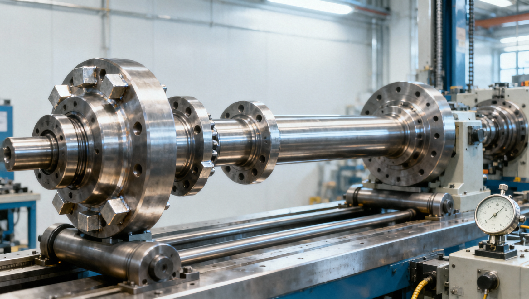
How Shaft Balance Affects Vibration in a Heavy Duty Drive Shaft
In high-load power transmission systems, shaft balance is a critical factor in controlling vibration, noise, bearing wear, and overall drivetrain reliability.
A precisely manufactured heavy duty drive shaft helps technical evaluators achieve smoother torque delivery and longer service life in demanding automotive, marine, and industrial applications.
Understanding how imbalance develops, how it is measured, and how precision forging and machining reduce its effects is essential when specifying performance-critical shaft assemblies.
What Technical Evaluators Need to Confirm First
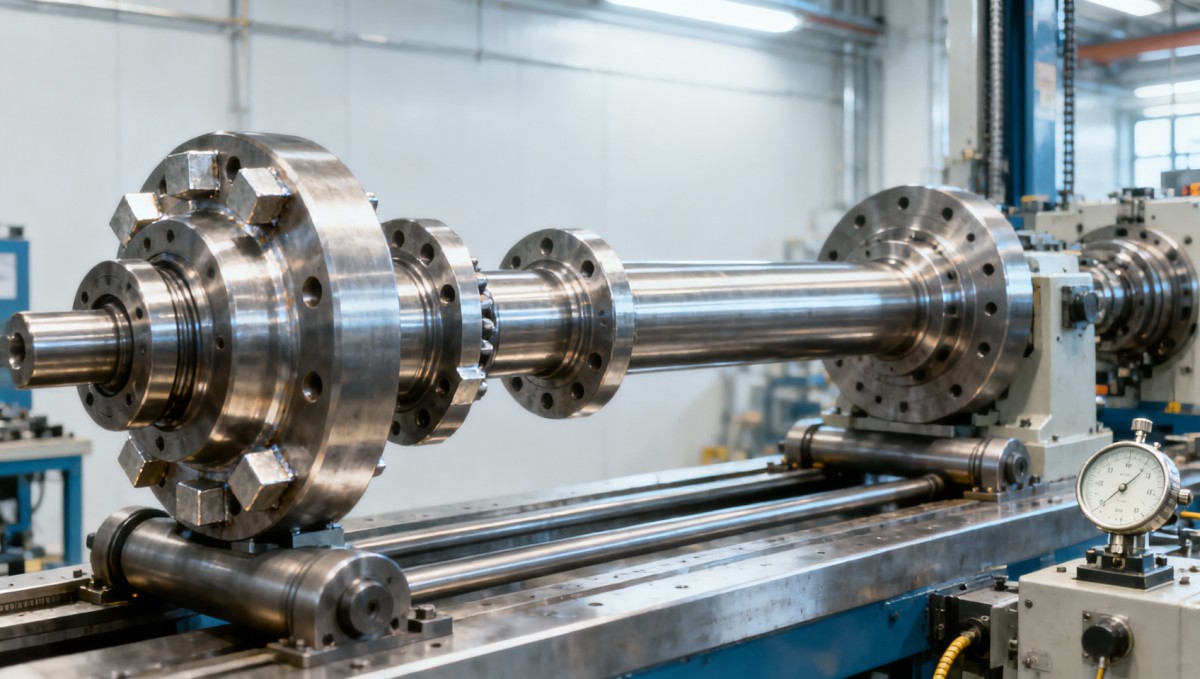
The core search intent behind heavy duty drive shaft balance is practical: determine whether a shaft can operate smoothly at its expected torque, speed, and duty cycle.
Technical evaluators usually need more than a statement that a shaft is balanced. They need measurable evidence, manufacturing controls, and a clear understanding of operating limits.
The most important question is whether residual imbalance will create forces large enough to affect bearings, universal joints, gearbox housings, seals, or connected equipment.
Balance quality matters because centrifugal force increases rapidly with rotational speed. A small mass error that appears harmless at low speed can become damaging at higher speed.
For a heavy duty drive shaft, the evaluation should consider shaft length, tube diameter, wall thickness, operating rpm, torque reversals, mounting geometry, and joint configuration.
A technically sound specification also distinguishes between component balance and assembled balance. A balanced tube alone does not guarantee that the complete driveline will run smoothly.
Flanges, yokes, splines, weld seams, balance weights, protective coatings, and fasteners can each shift the center of mass away from the rotational centerline.
The strongest purchasing decision is therefore based on residual unbalance limits, balancing method, inspection records, runout control, and validation under representative operating conditions.
Why Imbalance Produces Vibration and Mechanical Stress
Shaft imbalance occurs when the rotating mass is unevenly distributed around the intended axis of rotation. The shaft then generates a rotating centrifugal force during operation.
That force acts on bearings, joints, supports, and housings once per revolution. As speed rises, vibration can increase sharply because centrifugal force follows rotational speed squared.
A simplified relationship is F equals m times r times omega squared, where m is unbalanced mass, r is eccentricity, and omega is angular velocity.
This relationship explains why high-speed operation requires tighter balance control. Doubling rotational speed can increase imbalance force approximately four times when other variables remain constant.
In a heavy duty drive shaft, the resulting vibration may be felt through the vehicle frame, machine base, gearbox casing, steering structure, or operator platform.
Vibration is not merely a comfort or noise issue. Repeated dynamic loading can shorten bearing life, loosen fasteners, fatigue welds, damage seals, and degrade spline engagement.
The vibration frequency often corresponds to shaft speed, but the actual response depends on the complete drivetrain. Resonance can magnify a modest imbalance into a serious field problem.
Evaluators should therefore assess both forcing frequency and system natural frequencies. A shaft can meet a balance target yet still require design changes if critical speed is too close.
Static Balance and Dynamic Balance Are Not Interchangeable
Static imbalance means the shaft’s center of mass does not lie on its rotational axis. When supported on low-friction rollers, the heavy side tends to rotate downward.
Static balancing can identify a basic mass offset, but it does not fully describe long shafts or assemblies with mass errors at different axial locations.
Dynamic imbalance exists when principal inertia axes are misaligned with the intended rotating axis. It creates a couple that cannot be corrected at one plane.
Longer shafts, higher operating speeds, and multi-component assemblies generally require dynamic balancing. This process measures correction needs in two or more axial planes.
A short, low-speed shaft may operate acceptably after static correction. A long transmission shaft operating continuously at speed should normally be evaluated dynamically.
Dynamic balancing identifies where correction is needed and how much mass must be added or removed. Correction may involve welded weights, drilled material, or controlled machining.
Technical specifications should state the balancing condition clearly. Terms such as “balanced” without a grade, speed, correction plane, or acceptance criterion are not sufficient.
For critical applications, request documented balancing results for the final assembly configuration, including all production-intent yokes, flanges, splines, and attached hardware.
How Runout and Geometry Influence Balance Results
Balance is closely related to geometry, but the two are not identical. A shaft can have acceptable mass balance while excessive runout still produces vibration and cyclic loading.
Runout describes variation from the intended axis when the shaft is rotated and measured with an indicator. It may result from bending, eccentric machining, or distorted welding.
Radial runout can move the shaft surface relative to fixed supports. This creates displacement excitation even if mass distribution appears reasonably uniform.
Face runout at flanges is also important. An uneven flange mounting surface can introduce angular misalignment, causing joint motion and loading errors after installation.
Concentricity between journals, spline features, flange pilots, and shaft tube surfaces determines whether components share a common effective rotational axis.
Precision machining helps control these geometric relationships. However, the design datum strategy must be consistent from forging through machining, assembly, and final inspection.
Evaluators should request tolerances for straightness, total indicated runout, concentricity where applicable, and flange pilot geometry rather than relying on visual inspection.
A robust supplier will control runout before balancing. Adding weights to compensate for a bent or poorly located component can mask an underlying geometry problem.
Where Imbalance Commonly Enters a Heavy Duty Drive Shaft
Imbalance can originate in raw material variation, forging flow, machining setup, heat treatment distortion, welding, assembly orientation, or later service damage.
Forged shaft features can provide a more consistent starting geometry than highly variable fabricated components, particularly where hubs, flanges, or yokes carry major loads.
Material distribution must remain uniform around the centerline. Local inclusions, porosity, inconsistent wall thickness, or unplanned stock removal can affect rotating mass distribution.
Machining introduces risk when chucking, fixturing, or datum selection does not maintain the relationship between the shaft centerline and functional mounting features.
Welding is a frequent source of imbalance in tubular assemblies. Weld bead variation and thermal distortion can change both local mass distribution and shaft straightness.
Assembly orientation matters when yokes, flanges, and splined sections have their own residual imbalance. Clocking components incorrectly can make individual errors add together.
In service, dents, accumulated debris, missing balance weights, corrosion loss, and unauthorized repair welding can alter a previously acceptable heavy duty drive shaft.
Field failures should therefore be investigated with both balance testing and dimensional inspection. Rebalancing alone may not resolve vibration caused by damage or misalignment.
Critical Speed Can Turn a Minor Defect Into a Major Problem
Every rotating shaft has one or more natural bending frequencies. When operating speed approaches one of these frequencies, shaft deflection can rise dramatically.
This condition is commonly called critical speed. The shaft may whirl, increasing vibration even when residual imbalance is within an otherwise reasonable balancing tolerance.
Critical speed depends on shaft stiffness, unsupported length, mass distribution, bearing spacing, joint stiffness, mounting rigidity, and connected component inertia.
A larger diameter or thicker wall can increase stiffness, but design changes also affect weight, torsional behavior, cost, and packaging requirements.
Increasing shaft length generally lowers bending natural frequency. This is why long drivelines often need careful intermediate support design, balancing, and speed limitation.
Technical evaluators should compare the planned operating speed range against calculated or tested critical speeds. A margin is needed for manufacturing variation and transient overspeed.
The correct strategy may include changing shaft dimensions, adding a center bearing, modifying support stiffness, reducing operating speed, or improving balance quality.
Balance grade is valuable, but it cannot replace rotordynamic evaluation where shaft length, speed, and installed support conditions create a credible resonance risk.
How to Specify Balance Requirements for Procurement
A useful purchase specification begins with the actual operating envelope: continuous speed, maximum speed, torque, duty cycle, temperature, shock loading, and expected service life.
It should define the shaft assembly being balanced. Include flange types, yoke orientation, spline configuration, protective guards, fasteners, and any installed coupling components.
Specify whether static or dynamic balancing is required, the applicable balance quality grade, correction planes, and the maximum allowable residual unbalance.
Requirements should also identify the balancing speed or measurement method. The chosen approach must be suitable for the shaft dimensions and intended operating range.
Request measurable geometry controls alongside balance requirements. Straightness, radial runout, flange face runout, pilot diameter, and spline concentricity often affect final vibration behavior.
Inspection documentation should identify part number, revision, serial or batch traceability, measured values, acceptance limits, test equipment status, and inspector approval.
For high-consequence equipment, consider a first-article validation process. This can include balance reports, hardness verification, material certification, dimensional records, and functional run testing.
Technical teams should avoid specifying an unnecessarily tight balance tolerance without system justification. Excessive requirements can increase cost without improving real operating reliability.
Manufacturing Controls That Support Stable Shaft Performance
Consistent balance performance begins before final balancing. Material selection, forging design, controlled machining, and stable fixturing reduce variation that later correction cannot fully solve.
Precision forging can reduce machining allowance and support more consistent material utilization. It also helps create near-net functional forms for demanding rotating components.
For related rotating drivetrain applications, a Forged Ring can provide a controlled starting form for components requiring strength, concentricity, and reliable machining references.
Heat treatment must be managed carefully because thermal cycles can change dimensions and introduce distortion. Post-treatment inspection is important before final machining and balancing.
Machining processes should reference functional datums, not convenient but unrelated surfaces. This preserves alignment between mounting features and the final axis of rotation.
Where welding is necessary, controlled weld sequence, fixturing, heat input, and post-weld straightness verification reduce the risk of distortion and mass variation.
Final balancing should be performed after all features that materially affect rotating mass are complete. Coatings, plugs, hardware, and guards may require special consideration.
Process capability matters as much as one successful sample. Evaluators should ask how the supplier prevents recurring variation across production lots, shifts, and machine setups.
How to Diagnose Vibration in Service
When vibration occurs, first confirm whether its dominant frequency tracks shaft rotational speed. Speed-related vibration is a strong indicator of imbalance, runout, or rotating geometry issues.
Measure vibration at bearing locations, gearbox housings, frame members, and support brackets. Comparing amplitude and phase across points helps identify the likely source.
A vibration that rises sharply over a narrow speed range may indicate critical speed or resonance. A broad speed-related increase more often suggests imbalance or misalignment.
Inspect for missing balance weights, dented tubes, worn universal joints, loose fasteners, bent flanges, damaged splines, and contamination attached to rotating surfaces.
Check installation geometry before removing the shaft. Incorrect joint angles, poor flange seating, soft supports, or driveline misalignment can imitate an imbalance condition.
If field balancing is considered, establish whether the shaft is structurally sound first. Balancing a cracked, bent, or fatigued component can create an unsafe temporary result.
After corrective work, validate vibration over the complete operating range. A successful repair should reduce amplitude without creating a new resonance or transferring load elsewhere.
Document the root cause, not only the symptom. This information improves future shaft specifications, production controls, maintenance intervals, and supplier corrective actions.
Balancing Performance Against Cost and Reliability
The correct heavy duty drive shaft is not necessarily the one with the lowest quoted manufacturing cost or the tightest stated balance grade.
It is the shaft whose balance, geometry, strength, and critical-speed margin match the real operating system. Requirements should be proportional to application risk.
For low-speed equipment, robust construction and straightforward balance verification may be sufficient. For high-speed or long-span systems, deeper dynamic analysis becomes economically justified.
Unplanned vibration costs can exceed the initial shaft price quickly. Bearing replacement, gearbox repairs, downtime, warranty exposure, and repeated troubleshooting consume substantial resources.
Manufacturing methods that improve material consistency and reduce unnecessary machining can support both cost efficiency and repeatable shaft quality when controlled correctly.
Components such as a Forged Ring may also support efficient production of related transmission parts where strength and dimensional stability are essential.
Technical evaluators should compare suppliers using evidence: process control plans, balancing capability, inspection data, material traceability, and relevant experience with comparable loading conditions.
This approach produces a more defensible decision than evaluating only nominal dimensions, catalog claims, or unit price.
Conclusion: Balance Is a System Reliability Requirement
Shaft balance directly affects vibration because uneven rotating mass generates centrifugal force that increases rapidly with speed and excites the surrounding drivetrain structure.
For a heavy duty drive shaft, successful evaluation requires more than checking whether balancing occurred. It requires reviewing residual imbalance, runout, critical speed, assembly configuration, and process capability.
Dynamic balancing is especially important for long, high-speed, or multi-component shafts, while dimensional control prevents geometry defects from being hidden by mass correction.
The most reliable procurement decision combines clear performance requirements with documented inspection and manufacturing controls that maintain consistency from material preparation through final assembly.
By treating balance as part of total drivetrain design rather than a final cosmetic operation, technical teams can reduce vibration risk, protect connected equipment, and improve long-term service reliability.
Please give us a message