



Related Posts
Online Message
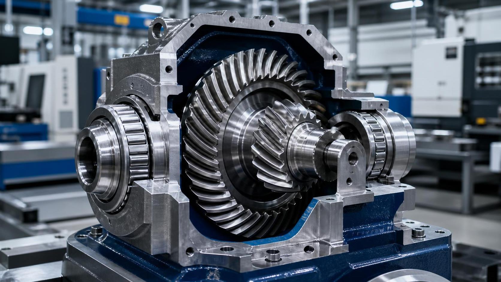
A spiral bevel gear is not judged by its outside diameter alone. Its geometry determines how torque is carried across the tooth flank, how the contact pattern moves under load, how much heat is generated, and whether a drivetrain remains acceptably quiet after thousands of operating hours. When a gear set is evaluated for an axle, wind gearbox, marine reducer, or right-angle industrial drive, small differences in spiral angle, tooth form, pitch, and mounting geometry can produce very different field results.
The practical question is not simply, “Is this gear machined accurately?” It is whether the complete gear geometry is appropriate for the load spectrum, speed range, housing stiffness, lubrication condition, and assembly tolerance of the application. A gear can look clean on a measuring report yet still create noise, edge loading, or premature pitting after installation if those factors have not been considered together.
How Spiral Bevel Gear Geometry Carries Torque
Unlike a straight bevel gear, a spiral bevel gear has curved teeth arranged along a spiral path across the face width. The teeth enter mesh progressively rather than all at once. This generally produces smoother torque transfer and allows several tooth areas to share load during engagement. That is one reason spiral bevel gear sets are widely used where shafts intersect at an angle and the transmission must carry meaningful torque without excessive vibration.
However, “more contact” is not automatically the same as “more capacity.” Torque capacity depends on the usable contact area under real deflection, not the theoretical contact area shown in a nominal model. Under load, the pinion shaft bends, bearings move slightly, the housing expands with temperature, and the tooth surfaces elastically deflect. A robust design leaves enough contact-pattern margin that these changes do not push load sharply toward the toe, heel, root, or tip of the tooth.
Several geometric features need to be assessed as a system:
- Module or diametral pitch: Larger teeth can generally support higher loads, but the resulting gear size, mass, and engagement behavior must still suit the drive.
- Face width: More face width can increase load-carrying area, but excessive width may become sensitive to shaft deflection and assembly error.
- Spiral angle: This affects overlap, smoothness, axial thrust, and the way load is distributed across the tooth face.
- Pressure angle and tooth depth: These influence bending strength, contact stress, sliding conditions, and sensitivity to alignment.
- Gear ratio and pinion tooth count: The pinion usually sees the highest number of stress cycles. A low-tooth-count pinion demands particularly careful attention to root strength and heat treatment.
A common mistake is to specify a wider gear face as a direct solution to high torque. In a rigid laboratory setup, that may improve the calculated rating. In a flexible gearbox or vehicle axle, the wider face can make the mesh less forgiving. If the mounting distance, bearing preload, or housing stiffness is not controlled, the gear may carry most of the load at one end of the tooth instead of using the full face width.
For this reason, tooth-contact pattern should be evaluated both at light marking load and, where the application justifies it, under representative torque. A centered pattern at no load is useful, but it does not prove that the pattern will remain safe under operating deflection.
Noise Control Begins With the Contact Pattern
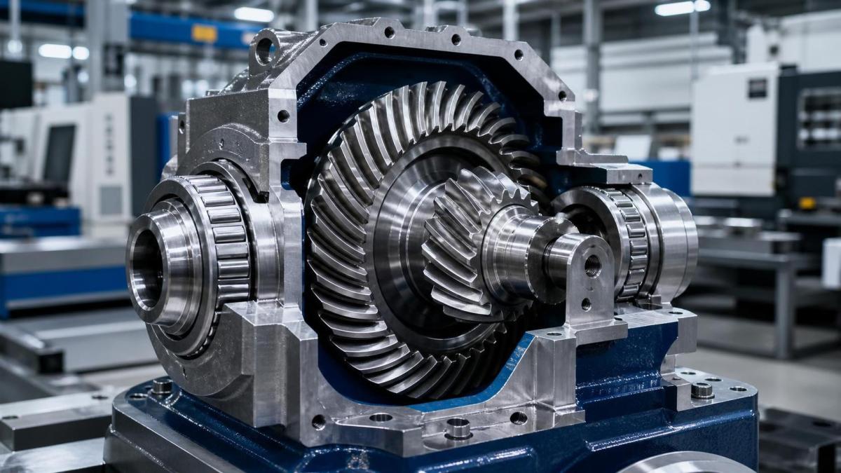
Gear noise is often treated as a surface-finish issue. Surface finish matters, particularly during run-in and at high rotational speed, but it is only one part of the picture. The dominant source of objectionable gear noise is usually variation in mesh excitation: small changes in tooth engagement create fluctuating forces that travel through shafts, bearings, and the housing.
Spiral bevel gears can operate quietly because their teeth engage gradually. That benefit is lost when the contact pattern is unstable, pitch variation is excessive, or the gear pair is mounted outside its intended position. A noise problem may therefore originate in the gear set, but it may also originate in bearing seats, case machining, shaft runout, preload variation, or thermal distortion of the assembly.
Three areas deserve close attention during technical review. First, check the declared mounting distance and pinion position rather than reviewing gear dimensions in isolation. Spiral bevel gear sets are sensitive to relative position. Second, ask how backlash is controlled after heat treatment and final finishing. Too little backlash risks scuffing and heat buildup; too much can increase impact and driveline clunk. Third, distinguish between tooth contact pattern and transmission error. A reasonable-looking marking pattern does not necessarily indicate low transmission error.
Controlled tooth modifications are frequently used to make the gear set more tolerant of load and assembly variation. Crowning, profile relief, and lead correction can help prevent edge contact and reduce excitation. These modifications should not be copied from another design without review. A correction that works in a compact automotive differential may be unsuitable for a large, slowly rotating wind-power stage with a different bearing arrangement and torque reversal profile.
Geometry Must Be Matched to Manufacturing Capability
Design intent only becomes useful when the manufacturing route can reproduce it consistently. The most important question for a supplier is not whether it can produce one acceptable sample. It is whether its process can maintain the intended geometry after forging, machining, heat treatment, finishing, and final inspection.
Precision forging can offer a strong starting point for selected gear blanks because it improves material utilization and can reduce the amount of turning required before tooth generation. It may also support more consistent grain flow compared with removing a large amount of material from bar stock, although the actual benefit must be verified against the material specification, forging design, and heat-treatment route. Forging does not replace tooth finishing. The tooth flanks still require the required accuracy and surface condition for the application.
Liaocheng Jiucheng Auto Parts Co., Ltd. combines precision-forging and mechanical-processing workshops for automotive, wind-power, marine, and industrial gear parts. That production combination is relevant when evaluating a spiral bevel gear program because blank quality, datum control, machining allowance, and tooth finishing should be planned as one process chain. A forged blank with poor datum stability can consume the tolerance needed for accurate gear cutting; a well-controlled blank gives the finishing operation a more reliable foundation.
Process review should follow the part from raw material to final inspection. Material chemistry and cleanliness, forging flow, normalizing or other pre-machining heat treatment, machining datum strategy, carburizing or induction-hardening requirements, distortion control, grinding or lapping strategy, and final cleaning all affect the finished gear. Omitting one of these checkpoints can make a later measurement result difficult to interpret.
Heat treatment deserves special caution. It creates the hardness profile needed for wear resistance and fatigue strength, but it can also alter tooth geometry. A supplier should be able to explain whether tooth corrections are planned before heat treatment, whether post-heat-treatment finishing is used, and how distortion trends are monitored across production batches. There is no universal answer because the appropriate route depends on gear size, steel grade, required case depth, load, and production volume.
What a Useful Inspection Package Should Show
A dimensional report containing only outside diameter, bore, and tooth count is not enough for a loaded right-angle gear set. The drawing should establish the gear geometry and the functional assembly conditions. Inspection records should then demonstrate that the delivered part is aligned with those requirements.
At minimum, review the tooth geometry method used by the supplier and confirm that the same system is understood by both sides. Spiral bevel gears are not interchangeable merely because they have the same ratio, module, and nominal shaft angle. Tooth system, hand of spiral, mounting distance, pinion offset, backlash target, and matched-pair requirements all matter.
Useful inspection evidence often includes tooth-profile and lead results, pitch or index measurement, runout relative to functional datums, mounting distance verification, backlash checks for matched sets, contact-pattern records, and hardness or case-depth results where heat treatment applies. For noise-critical applications, rolling tests or noise-and-vibration testing may also be appropriate. The test condition should be stated clearly; a no-load rolling test and a loaded NVH test answer different questions.
Standards should be selected according to the product specification and customer requirement. ISO and AGMA gear-rating methods are commonly used references for evaluating bending and contact fatigue, but their inputs must reflect the actual duty cycle and assembly arrangement. Quoting a standard without defining load factors, material data, quality level, lubrication assumptions, and design life does not create a meaningful rating.
When a Spiral Design Is the Wrong Choice
Spiral bevel gears are not the default answer for every intersecting-shaft drive. They can offer smooth engagement and good load-sharing behavior, but they also produce axial thrust that must be supported by the bearing and housing arrangement. Their manufacture and matching requirements are more demanding than those of many simpler gear types.
For a low-speed, lightly loaded mechanism where cost, easy replacement, and simple production are the main priorities, a straight bevel gear or another transmission layout may be sufficient. In a parallel-shaft section of a gearbox, a conventional Spur gear may be the more direct and economical choice because it does not perform the same right-angle transmission function. Comparing these gear types only by “strength” misses the point; shaft arrangement, noise target, speed, space, and serviceability should lead the decision.
There is also a limit to what geometry can correct. If the gearbox housing is too flexible, bearing fits are inconsistent, lubricant viscosity is unsuitable at operating temperature, or the assembly process shifts pinion position, a highly refined gear flank cannot fully compensate. In field troubleshooting, this is why replacing the gear pair without checking the supporting system sometimes fails to remove the original noise.
A Practical Review Before Releasing Production
Before approving a spiral bevel gear supplier or releasing a drawing, establish the actual operating envelope: peak and continuous torque, speed, duty cycle, reversing load, expected life, temperature range, lubrication method, and permissible noise level. Then review the complete mesh arrangement, including housing and bearing constraints. This step is more valuable than asking for a generic “high precision” claim.
Next, confirm how the gear pair will be controlled in production. Is it supplied as a matched set? Which functional dimensions define assembly? What final tooth-finishing method is used? How are contact pattern and backlash checked? How is heat-treatment distortion handled? Clear answers to these questions usually reveal whether the supplier understands functional gear quality rather than only part dimensions.
For high-volume automotive programs, repeatability and traceable process control often carry as much weight as an excellent prototype result. For wind-power, marine, and industrial transmissions, the load spectrum, service access, and consequence of downtime may justify more conservative geometry, more extensive validation, or stricter final testing. The required solution should follow the service condition, not a generic quality label.
Near the end of the evaluation, return to the working fundamentals: the best spiral bevel gear is the one whose tooth geometry, material condition, finishing quality, and mounting arrangement remain stable together under the loads it will actually see. That is where torque capacity and quiet operation are decided.
Please give us a message