



Related Posts
Online Message
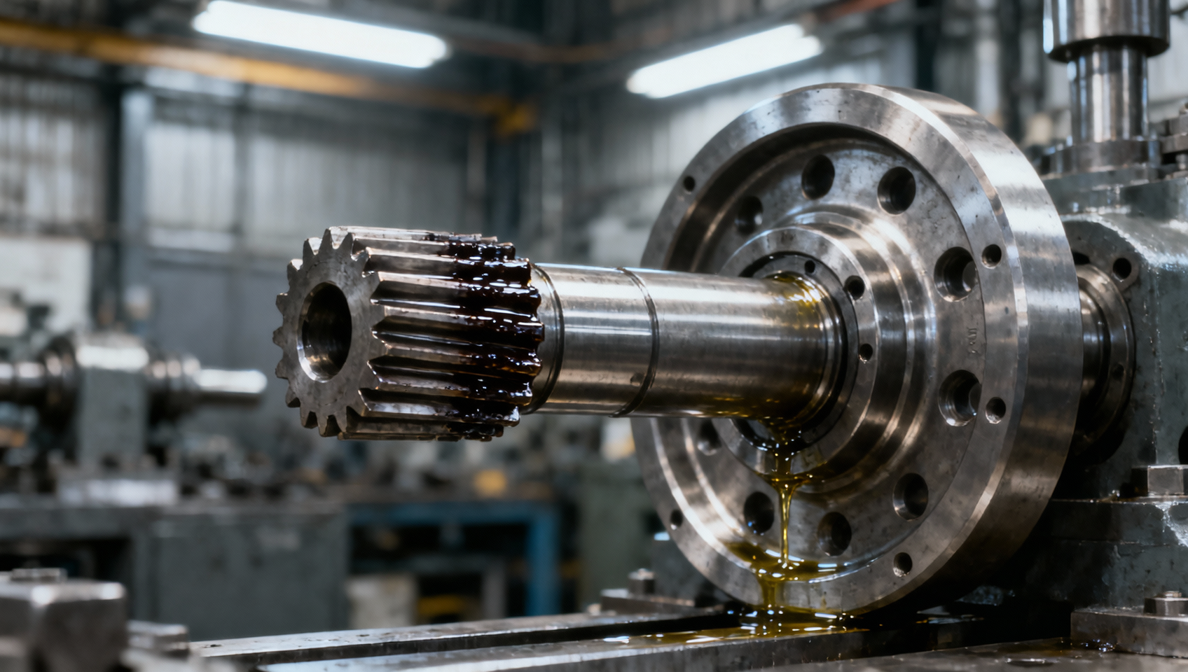
A 12 spline shaft connection develops fretting damage when the mating shaft and hub undergo repeated microscopic relative motion while remaining nominally engaged. The visible result may be reddish-brown or black debris, polished flank bands, local pitting, worn tooth profiles, or corrosion at the spline roots. The more important issue is not cosmetic surface damage: fretting progressively reduces effective contact area, alters backlash and load sharing, and can initiate fatigue cracks in a torque-transmitting component.
The designation “12 spline shaft” identifies the number of teeth, but it does not define the spline geometry, fit class, flank form, material, hardness, or torque capacity. A 12-tooth straight-sided spline, an involute spline manufactured to ISO 4156, ANSI B92.1, or DIN 5480 principles, and a proprietary automotive spline can all fail by fretting for different dimensional reasons. Root-cause analysis therefore has to start with the actual drawing and inspection requirements rather than the tooth count alone.
Why fretting occurs in an apparently fixed connection
Fretting requires three conditions: contact pressure, cyclic loading, and a very small sliding displacement between contacting surfaces. In a spline connection, the displacement is often only a few micrometres. It may be too small to feel as looseness during a basic inspection, yet sufficient to disrupt surface films and produce abrasive oxide particles over many load cycles.
A properly fitted spline is designed to transmit torque through controlled flank contact. Under a steady, unidirectional torque, the loaded flanks can remain relatively stable. Damage becomes more likely when torque reverses, fluctuates sharply, or is repeatedly applied and released. Each reversal moves the contact zone from one flank toward the opposite flank. If clearance, elastic deformation, poor alignment, or insufficient engagement allows the shaft and hub to rock, the contact interface repeatedly slips instead of remaining in a stable loaded condition.
The debris created during this process is highly damaging. Fresh metallic contact breaks down oxide films; exposed material oxidises; and hard oxide particles become trapped between the flanks. The joint then shifts from adhesive surface damage toward three-body abrasion. This is why a spline can show both dark fretting corrosion and bright, heavily polished wear areas at the same time.
Insufficient or uneven flank contact is the central mechanical cause
Low effective contact pressure is often described as a loose fit, but the condition is more specific than excessive backlash. A spline may meet a simple major-diameter or minor-diameter check and still have poor flank contact because of tooth-thickness variation, incorrect pressure angle, lead error, profile error, taper, or inconsistent coating thickness. In an involute spline, torque should be shared across the intended working flanks. When only a narrow edge or a small number of teeth carry load, local pressure rises while the remaining teeth contribute little to torque transmission.
Uneven contact creates a damaging sequence. Local overstress causes slight plastic deformation or polishing at the high points. As the interface wears, clearance increases. The shaft then has more freedom to oscillate under torsional vibration, further increasing micro-slip. A connection that initially produces only light discoloration can therefore deteriorate quickly once its fit has changed.
Contact pattern inspection is more informative than checking only tooth count and nominal dimensions. Prussian blue, approved contact-marking compounds, or controlled engineering methods can reveal whether contact is centered on the flanks, concentrated near the tooth tip or root, or biased toward one end of the engagement. Such checks must be interpreted carefully: excessive marking compound, incorrect assembly force, or non-representative loading can produce misleading patterns. Still, a clear one-sided or edge-loaded pattern is a strong indication that geometry or assembly alignment deserves investigation.
Micro-movement is often generated outside the spline itself
A spline can be manufactured correctly and still fret because the surrounding assembly permits movement. Bent shafts, eccentric hubs, bearing clearance, housing distortion, inadequate support length, and poor mounting-face flatness can all impose alternating radial or angular displacement on the joint. In these cases, the spline is the location where damage becomes visible, not necessarily the origin of the problem.
Angular misalignment is particularly harmful in short engagement lengths. It shifts load toward one end of the spline, producing end-face polishing and localized wear near the first or last engaged teeth. Parallel offset can produce a different pattern: contact may appear concentrated on opposite sides of the circumference, often accompanied by uneven tooth flank wear. A damaged spline should therefore be assessed alongside bearing condition, shaft runout, hub bore geometry, and the stiffness of the components supporting the connection.
Torsional vibration is another frequently underestimated driver. Cyclic torque from engines, gear trains, pumps, reversing drives, sudden braking, or intermittent loads can cause repeated stick-slip at the flanks even where mean torque is modest. The risk is elevated when a connection operates near a torsional resonance, when a driveline has excessive backlash, or when control settings create abrupt torque reversals. Static torque capacity calculations do not identify this problem by themselves.
Lubrication failures do more than increase friction
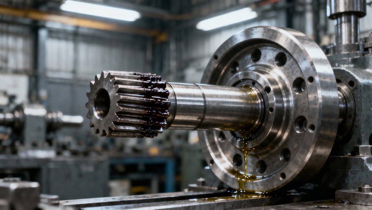
Lubrication can reduce friction, limit oxide formation, carry away wear particles, and help prevent corrosive attack. It cannot compensate for a severely loose or misaligned spline, but its absence accelerates damage once micro-movement begins. Dry assembly is particularly vulnerable where torque reversal, vibration, or environmental moisture are present.
The correct lubricant depends on load, temperature, speed, service environment, material pair, and whether the joint is intended to slide during assembly only or operate with relative motion. A grease selected solely for general-purpose bearing service may not provide adequate adhesion or anti-fretting performance on spline flanks. Conversely, excessive grease can mask early debris during inspection and may interfere with other assembly requirements. The engineering specification should define lubricant type, application quantity, re-lubrication interval where relevant, and protection against contamination.
Contaminants can turn a marginal interface into an abrasive one. Water promotes corrosion, while dust, machining chips, sand, and degraded grease introduce particles into the contact zone. Damaged seals, poor storage, open handling before assembly, and cleaning residues all deserve consideration. If fretting is concentrated near an exposed spline end, ingress is more likely than when the damage is uniform throughout the engagement.
Surface condition and treatment can determine how quickly damage progresses
Surface roughness must support stable load-bearing contact without creating excessively high asperities. A very rough flank surface can wear in rapidly and generate debris. An extremely smooth surface is not automatically better if it is combined with inadequate lubrication or a fit that permits motion. The relevant objective is a controlled finish consistent with the spline design, manufacturing method, and intended lubrication regime.
Hardness mismatch also affects damage behavior. A softer hub may show rapid flank deformation, while a hardened shaft can retain its form but promote wear of the mating member. Insufficient case depth, poor heat-treatment uniformity, grinding burn, decarburization, or uncontrolled post-treatment distortion may reduce fatigue resistance and alter contact geometry. These issues should be evaluated through the applicable material and process specifications rather than by relying on nominal hardness alone.
Coatings require equal care. Phosphate, manganese phosphate, zinc-based treatments, nitriding, and other surface systems may be used for corrosion resistance, run-in behavior, or wear performance depending on the application. A coating that is too thick or uneven can reduce effective clearance and cause assembly damage; a brittle or poorly bonded coating can generate debris; and a treatment applied after final machining can alter the functional fit. The dimensional effect of surface treatment must be included in the tolerance strategy.
Large rotating equipment provides a useful parallel: interfaces around drive systems, including components such as Slewing bearing rings, must be assessed as part of a complete load path. Local wear at a shaft-to-hub spline may reflect deflection, mounting error, or variable loading elsewhere in the assembly. Treating only the visible interface without checking the support structure can leave the underlying cause unchanged.
Manufacturing and assembly errors that create fretting risk
Fretting investigations often uncover a combination of small deviations rather than one dramatic defect. The following conditions are especially relevant for a 12 spline shaft connection:
- Incorrect spline fit: Excessive space width, undersized tooth thickness, or an unsuitable fit class increases circumferential movement under reversing torque.
- Lead, profile, or indexing error: These errors prevent equal load distribution across the teeth and may cause only a few flanks to carry most of the load.
- Inadequate engagement length: Reduced overlap lowers the available load-bearing area and makes the joint more sensitive to angular misalignment.
- Assembly damage: Forced installation, hammering, burrs, dented tooth tips, or handling damage can create local high spots and prevent full seating.
- Wrong orientation or incomplete seating: A shaft that is not fully engaged may appear assembled but operates with reduced spline length and a higher bending moment.
- Uncontrolled rework: Hand dressing, local polishing, or removal of corrosion products can change tooth geometry and conceal evidence needed for root-cause analysis.
Inspection plans should distinguish between attributes that confirm interchangeability and those that protect functional load transfer. Go/no-go gauges can be useful for production control, but they may not reveal all errors affecting contact distribution. Depending on the design, functional gauging, coordinate measurement, profile measurement, runout verification, and controlled contact checks may all be necessary. The selected method should correspond to the drawing, the applicable spline standard, and the failure consequence of the assembly.
How damage appearance helps narrow the cause
Damage morphology can guide the investigation, although it should not be treated as conclusive evidence in isolation. Uniform dark staining over most loaded flanks suggests broad micro-motion and possible inadequate fit or lubrication. Bright wear concentrated at one end of the engagement points more strongly to angular misalignment, shaft deflection, or distorted support components. Wear on only a limited number of adjacent teeth can indicate indexing error, hub distortion, or uneven torque introduction.
Reddish corrosion products are common where steel surfaces are exposed to moisture and oxygen, but color alone does not establish the failure mechanism. Brown debris may result from ordinary corrosion combined with wear, while dark oxide debris may be generated through repeated fretting contact. Microscopic examination, debris analysis, and a review of service environment can clarify whether corrosion is a primary initiator or a secondary consequence of mechanical movement.
Cracks at spline roots require urgent attention because fretting damage can create local stress concentrations and remove protective surface layers. Root cracking may also result from overload, improper heat treatment, or a geometric stress raiser unrelated to fretting. The distinction matters: replacing the shaft without correcting a loose hub, severe misalignment, or overload condition can lead to recurrence.
Control measures should be tied to the actual failure mechanism
When the main driver is excessive clearance, the corrective action is to restore the specified functional fit through controlled replacement or redesign. Increasing lubricant quantity alone will not make an under-fitted spline reliable. When contact is concentrated at one end, the priority is to measure alignment, support stiffness, shaft straightness, bearing condition, and assembly seating. If debris and corrosion dominate at an exposed end, sealing, storage, cleaning, and lubricant retention may require improvement.
For new or revised assemblies, the design review should verify torque spectrum rather than nominal torque alone. Reversal frequency, transient peaks, torsional vibration, bending load, temperature, and expected service contamination all affect spline behavior. The selected standard—such as ISO 4156 for relevant involute spline applications, ANSI B92.1 where specified, or DIN 5480 for metric involute systems—provides geometry and tolerance frameworks, but it does not eliminate the need to evaluate the actual duty cycle and supporting structure.
Traceability is valuable after any fretting finding. Retain evidence of shaft and hub lot numbers, material certification where required, heat-treatment records, surface-treatment status, inspection results, assembly torque or seating records, lubricant identification, and service history. Photographs should document the as-found condition before cleaning. This record makes it possible to separate a dimensional nonconformance from a lubrication, environmental, or system-level loading issue.
A 12-spline connection does not fail simply because it has twelve teeth. Fretting begins when the intended torque-transmitting contact becomes a repeatedly moving interface. Controlling fit, flank geometry, engagement, alignment, lubrication, surface condition, and the external load path is what prevents the small movements that ultimately produce wear, corrosion debris, looseness, and fatigue risk.
Please give us a message