



Related Posts
Online Message
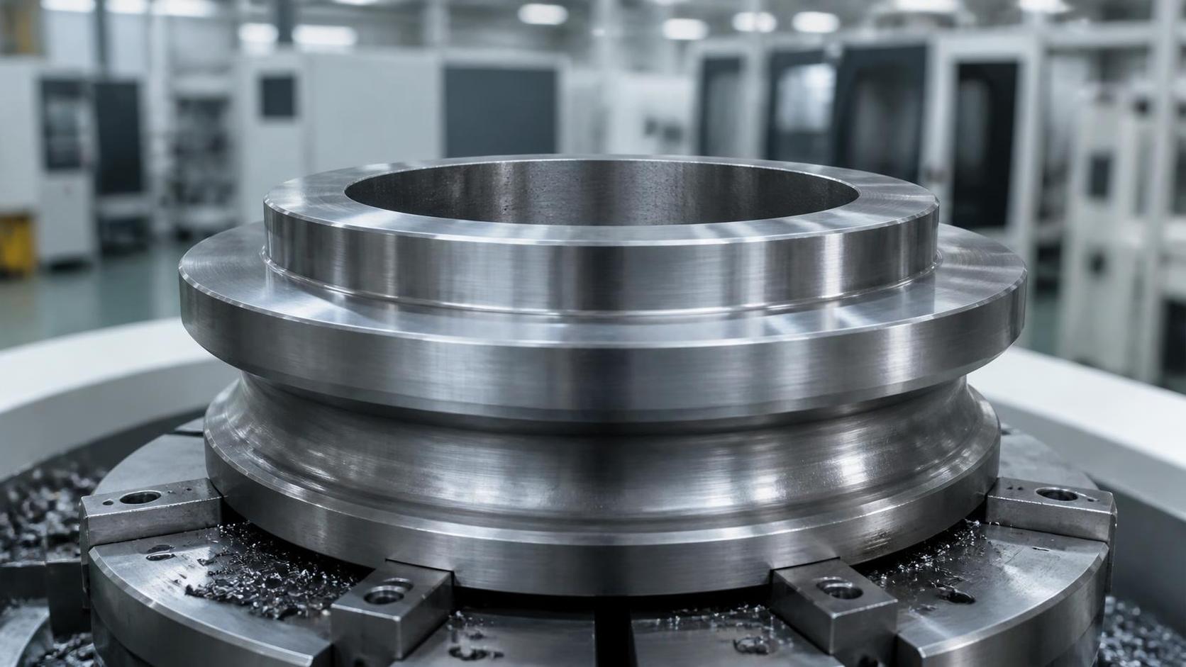
For technical evaluators assessing complex ring profiles, Forged Shaped Rings offer a practical route to lower machining waste while improving material utilization, dimensional consistency, and production efficiency. By forming near-net geometries before finishing, manufacturers can reduce turning allowances, conserve energy, and control total part cost—especially for demanding automotive, wind power, marine, and transmission applications.
The key point is not simply that forging uses less material than machining a ring from solid stock. The real advantage appears when a ring has profile features that make conventional bar-to-ring machining inefficient: stepped outside diameters, internal hubs, flange-like sections, local thickening, variable wall sections, grooves, or interfaces that must later carry gear teeth, splines, bearings, or bolted connections.
In such cases, the technical question is whether the forging can place material close enough to the functional geometry that machining becomes a finishing operation rather than a bulk-removal operation. That decision affects billet weight, press capacity, die investment, heat-treatment response, machining cycle time, scrap handling, and ultimately the repeatability of the finished component.
Why complex profiles create disproportionate machining waste
A simple cylindrical ring can often be produced from seamless rolled ring stock with manageable machining allowances. The situation changes when the final component includes several diameters or axial steps. If a forged blank remains a simple rectangular cross-section, the starting diameter and wall thickness must accommodate the largest local section. Every smaller section is then created by removing material.
Consider a transmission ring with a thick bearing seat on one side, a thinner central web, and a reinforced rim intended for subsequent gear cutting. Machining the part from a uniform ring blank means that the web and non-bearing areas may lose substantial material as chips. The same principle applies to marine drivetrain components with flange transitions, planetary-carrier ring elements, and wind gearbox rings with localized stiffness requirements.
This approach has several hidden penalties:
- More purchased steel is converted into chips rather than into the finished part.
- Longer rough-turning cycles consume machine capacity that could be used for value-adding finishing work.
- High material-removal volumes increase tool wear and chip-management requirements.
- Large allowances can make it harder to maintain stable thermal conditions during machining.
- A heavier starting blank may require larger handling equipment and reduce furnace loading efficiency.
Forged Shaped Rings address this problem by using die-controlled deformation to create major section changes before machining. The resulting blank is not necessarily a finished part, nor should it be treated as one. It is a process-optimized preform designed to leave metal only where the final component needs it, while retaining enough allowance for heat-treatment distortion, datum establishment, and final machining.
What “shaped” should mean in a forging specification
The term can be used broadly, so it needs to be translated into measurable geometry during quotation and process review. A shaped ring may include one or more of the following:
- Stepped inner or outer diameters;
- Axial shoulders and collars;
- Raised rims or reinforced zones;
- Flange-like sections for attachment or load transfer;
- Annular grooves formed before final machining;
- Non-uniform wall thickness around the axial section;
- Preformed hub interfaces intended for later broaching, gear cutting, or spline generation.
Not every feature belongs in the forging die. Small radii, narrow grooves, sharp corners, fine tooth geometry, tight bearing fits, and precision sealing surfaces usually remain machining operations. Trying to forge these details can increase die complexity, accelerate wear, and reduce process robustness without creating a meaningful material-saving benefit.
The useful boundary is usually determined by feature scale and functional tolerance. Large-volume features that would otherwise require deep rough turning are strong candidates for preforming. Features that control final assembly, contact stress, sealing, or gear geometry should generally be left with adequate machining stock.
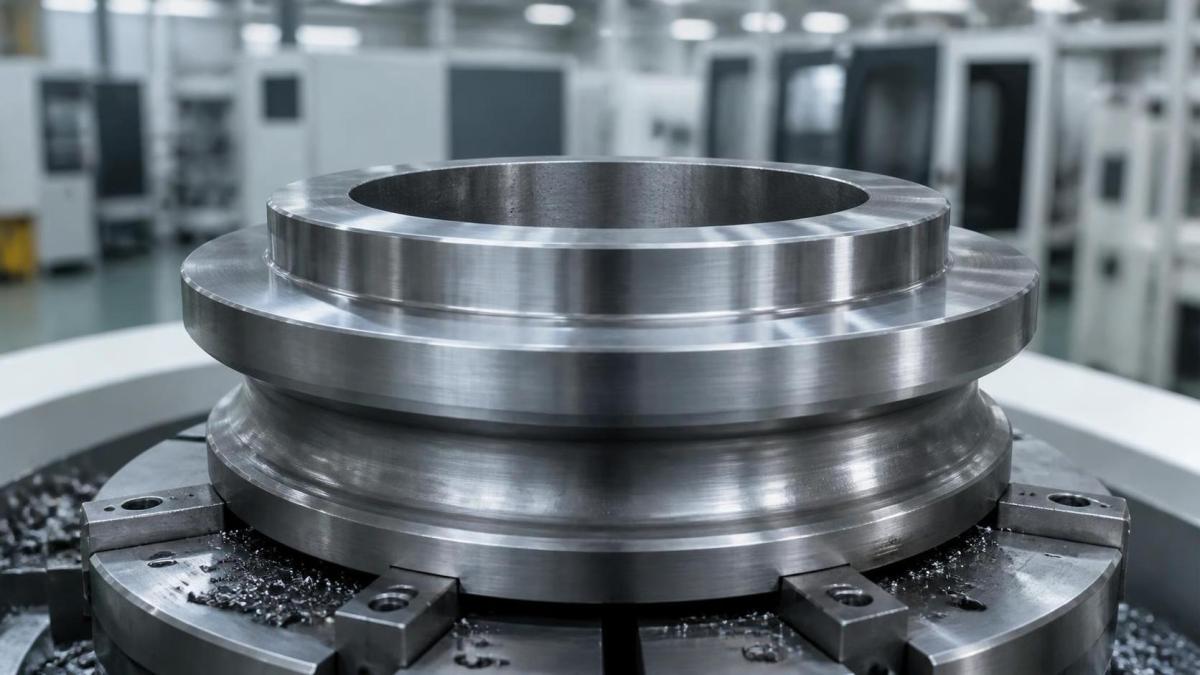
The material-flow advantage is more important than the visual shape
Near-net geometry is only one part of the case for forging. Controlled deformation can also orient grain flow around the ring profile, which may support fatigue resistance and load-carrying performance when the process is properly designed. This matters in components subject to cyclic torque, shock loading, or alternating bending loads.
However, grain-flow arguments should not be accepted as a generic quality claim. Their relevance depends on the steel grade, reduction ratio, forging temperature window, deformation path, cooling practice, heat treatment, and the location of critical stresses in the final part. A shaped ring with inadequate deformation or poorly controlled temperature may not deliver the expected metallurgical benefit.
For this reason, a capable supplier should be able to explain more than the final outline. The technical review should cover billet size, heating method, preforming sequence, die-fill strategy, expected flash or trimming condition, grain-flow direction where relevant, and the inspection plan after forging and heat treatment.
Where shaped-ring forgings are most likely to outperform conventional blanks
The strongest candidates are parts where the finished geometry has substantial rotational symmetry but contains axial profile complexity. Automotive drivetrain rings, differential-related components, reducer elements, and gear blanks are common examples. A ring that will later receive external gear teeth may benefit from a forged rim that is close to the required tooth-root diameter, while preserving machining stock for gear cutting and finishing.
Wind-power gearbox applications can also be suitable, particularly where heavy-section transitions must be integrated with large-diameter ring geometry. Here, the decision should consider more than raw material savings. Large parts may face demanding requirements for cleanliness, internal soundness, heat-treatment uniformity, and traceability. A low-waste preform is not beneficial if it introduces a higher risk of internal defects or distortion that cannot be economically corrected.
Marine and industrial transmission applications often present another favorable condition: lower annual volume but relatively expensive material and long machining cycles. Even where die amortization is less attractive than in automotive programs, a shaped forging may still be justified if it removes enough rough-machining time or reduces the size of the starting billet.
For shaft-and-ring assemblies, the interface should be reviewed as a system rather than as isolated parts. For example, the forging approach used for an associated Spline Shaft can influence the preferred datum strategy, hardness pattern, and machining sequence of the mating ring component. This is especially relevant where spline fit, torque transfer, and bearing location share a common axial tolerance chain.
The break-even point is determined by more than annual volume
Annual quantity matters because shaped forgings may require dedicated tooling, but volume alone is an incomplete selection rule. The comparison should include the total conversion route.
A practical evaluation begins with two process maps: one for the existing machined blank and one for the proposed forged profile. Each map should quantify purchased weight, forged weight, finished weight, rough-machining removal, finishing allowance, machining minutes, tooling consumption, heat-treatment stages, handling operations, and expected yield.
Material utilization can then be expressed simply as finished-part mass divided by input material mass. The calculation is useful, but it must not obscure cost drivers. A route with a lower input weight may still cost more if it needs complicated dies, additional reheating, difficult trimming, or unusually high rejection rates. Conversely, a higher-cost forging can be justified if it eliminates a machining bottleneck or stabilizes quality in a component with high downstream value.
Three conditions usually favor investment in a shaped preform:
- The part has large, repeatable machining removal in non-critical areas.
- The geometry can be formed with realistic draft angles and radii.
- The program has sufficient volume, part value, or machining constraint to recover tooling and qualification costs.
Low-volume replacement parts, frequently changing designs, and profiles dominated by fine features often remain better suited to standard rings, open-die forgings, or machining from available stock.
Machining allowance cannot be reduced by assumption
A common implementation mistake is to convert a conventional ring into a shaped forging and immediately reduce all allowances to the lowest theoretical value. This can create shortages after heat treatment, especially on parts with asymmetric section thickness or hardening-related distortion.
Allowances should be assigned by surface function and process risk. Bearing journals, gear-reference diameters, sealing lands, and concentric locating surfaces need enough material for cleanup after all distortion-inducing steps. Non-functional outer surfaces may permit tighter preform control. The correct allowance is therefore not uniform around the ring.
Before production release, the proposed process should establish capability for:
- Outside and inside diameter variation after forging;
- Ovality and runout relative to the intended machining datums;
- Axial face variation and shoulder position;
- Wall-thickness consistency at thick-to-thin transitions;
- Distortion after normalizing, quenching and tempering, carburizing, nitriding, or other specified thermal cycles;
- Surface condition in areas that must later be machined or inspected.
The machining route must also be planned around datum survival. If the forged profile includes multiple steps, it may be tempting to use a near-net shoulder as an early locating surface. That can be efficient, but only if the forging process controls that feature reliably. Otherwise, the first operation should establish stable reference faces and a true bore before subsequent turning or gear cutting.
Design details that can make or break the forging route
Several drawing features are routinely underestimated during early feasibility work. Sharp transitions are a concern because forging requires radii to maintain material flow and protect die life. If the finished part needs a sharp corner, the drawing should distinguish between a forged transition radius and the final machined corner requirement.
Draft angle is another issue. External and internal surfaces may require draft for die release, depending on the process route. A design that insists on zero draft everywhere can force unnecessary machining or make closed-die forming impractical. The right response is not automatically to accept more draft; it is to identify which surfaces are functional, which will be machined, and which can retain a forged finish.
Section transitions need special attention. An abrupt change from a thin web to a heavy rim can create uneven die filling and non-uniform cooling. It may also increase quench distortion. In some cases, a modest geometric change in the preform—not necessarily in the final part—can improve process stability while preserving the finished design intent.
Steel selection should be reviewed alongside shape complexity. Hardenable alloy steels used for gears and transmission parts may have very different forging and heat-treatment behavior from carbon steels or stainless grades. Material specifications, cleanliness requirements, ultrasonic inspection criteria, and heat-treatment standards must remain aligned with the actual service load and customer drawing. Where requirements refer to a specific standard or acceptance class, the latest applicable revision should be confirmed rather than inferred.
Quality planning should follow the actual failure modes
Visual inspection alone is insufficient for complex forgings. The inspection plan should reflect the risks associated with the part’s size, material, geometry, and service duty. Typical controls may include chemical analysis and heat identification, dimensional checks after forging, magnetic-particle inspection where surface-breaking discontinuities are a concern, ultrasonic examination where internal soundness is critical, and metallographic verification when grain size, decarburization, or microstructure is specified.
Traceability is particularly important for gearbox and drivetrain components. A robust route connects raw material heat number, forging batch, thermal cycle, inspection records, machining lot, and final part identification. For export programs, documentation expectations should be agreed before qualification. Requirements often differ between an automotive production program, an industrial gearbox customer, and a marine project subject to class-related documentation.
It is also worth separating forging defects from machining symptoms. A runout problem seen during gear cutting may originate in datum selection, forging ovality, heat-treatment distortion, fixture clamping, or a combination of these factors. Root-cause analysis should follow the complete manufacturing sequence rather than assigning responsibility based solely on where the defect became visible.
A disciplined trial is more useful than a theoretical saving claim
The most reliable way to validate Forged Shaped Rings is through a controlled pilot run using representative material and the intended heat-treatment route. The trial should compare actual blank weight, machining time, tool consumption, dimensional cleanup rate, distortion, and reject causes against the conventional blank. It should also assess whether any apparently saved machining time has shifted into extra setup, clamping, or inspection complexity.
A successful result is not merely a lighter blank. It is a stable manufacturing route in which the forged profile consistently leaves sufficient stock on critical surfaces, reduces non-value-added metal removal, and does not introduce quality risks that outweigh the material benefit.
For complex rotational parts, shaped forging is therefore best treated as a manufacturing-engineering decision, not a purchasing substitution. When profile geometry, material behavior, machining allowances, and inspection requirements are developed together, the process can reduce waste without compromising the dimensional and metallurgical controls that high-load applications require.
Please give us a message