



Related Posts
Online Message
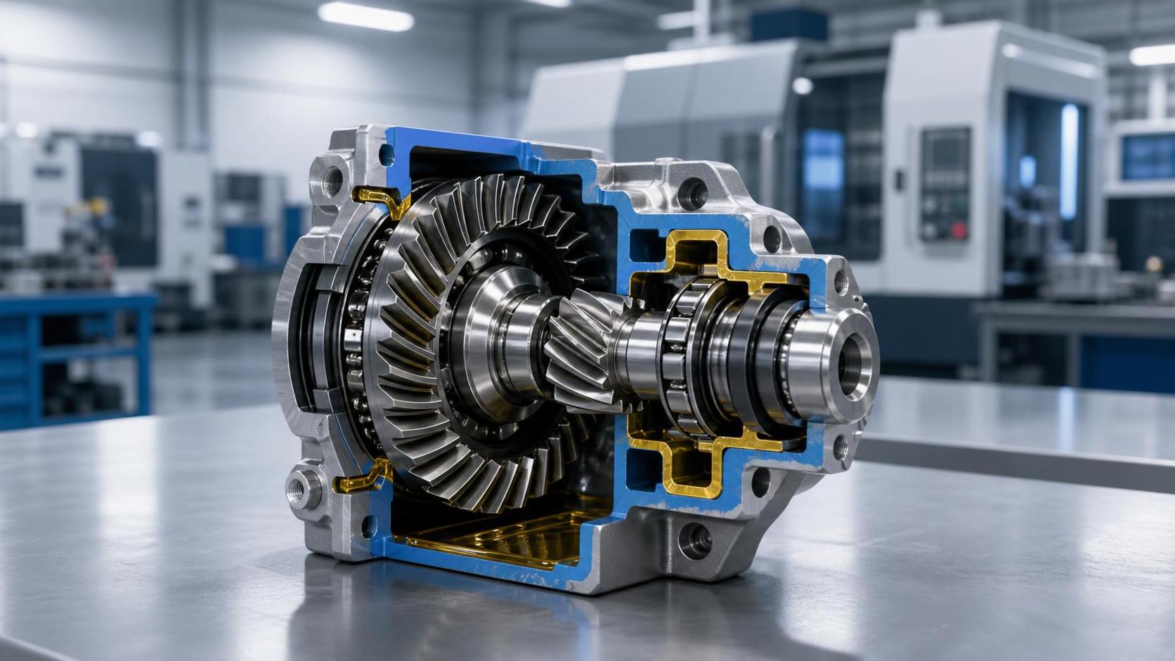
In compact right-angle drive systems, the choice of an internal bevel gear can influence far more than the direction of rotation. It affects packaging space, torque capacity, assembly access, bearing layout, noise behavior, and the amount of downstream machining required to bring a design into production. For project managers, this is rarely a simple component-selection exercise. It is a decision that connects system performance with sourcing risk, manufacturing feasibility, and lifecycle cost.
Right-angle drives appear in places where machinery must work hard within limited envelopes: compact reducers, marine auxiliary mechanisms, automation equipment, steering-related assemblies, specialized transmissions, and certain wind-power or industrial gearbox arrangements. In these projects, the gear set often becomes the point where ambitious space targets meet the practical limits of forging, machining, inspection, and assembly.
An internal bevel gear arrangement is particularly relevant when the design needs to transmit motion through approximately 90 degrees while keeping the driven member positioned around, rather than beside, part of the gear train. Used thoughtfully, it can help engineers create dense, protected drivetrain layouts. Used without a clear understanding of load paths and manufacturing constraints, it can create difficult tooth-cutting operations, inspection challenges, and costly late-stage revisions.
Understanding What “Internal Bevel Gear” Means in a Real Design Discussion
The term internal bevel gear is sometimes used broadly in project conversations, and that can cause confusion before design work has even begun. Conventional bevel gears generally feature external teeth on conical pitch surfaces. In compact transmission discussions, however, “internal” may describe a gear with teeth formed on an inward-facing conical surface, a ring-like bevel member, or a functionally similar enclosed angular gear interface.
Before issuing drawings or requesting quotations, the project team should define the intended geometry in unambiguous terms: tooth location, pitch-cone relationship, mating pinion arrangement, shaft angle, rotation direction, and whether the gear is a true internal conical form or a related face-gear-style solution. A supplier cannot reliably assess tooling, forging allowance, tooth generation, or inspection methods from the word “internal” alone.
This early clarification matters because an internal-tooth configuration changes the manufacturing conversation. Tool access can be restricted, root geometry may be harder to finish, and heat-treatment distortion may have a stronger effect on contact pattern than it would in a more open external gear design. The compact package may be attractive, but it must be matched with a process route that can actually produce the intended geometry consistently.
Where This Gear Concept Earns Its Place
Not every right-angle drive needs an internal bevel arrangement. Standard spiral bevel or hypoid gear pairs remain effective choices when there is room for two externally toothed gears and straightforward shaft support. Internal bevel gear concepts become more compelling when the surrounding architecture places a premium on enclosure, coaxial relationships, or protected torque transfer.
1. Enclosed right-angle reducers with limited radial space
A compact reducer often needs a robust housing wall, bearings, seals, and lubrication passages while still fitting inside a defined machine envelope. If the driven gear can be integrated into a ring-like or inward-facing structure, the designer may reduce the amount of external radial build-up around the gear mesh. This is valuable in machinery where the drive must sit close to frames, guards, actuator bodies, or adjacent process equipment.
The benefit is not simply “smaller is better.” The real advantage is the freedom to redistribute space. A few millimeters saved at the outside of the gearset may create room for a larger bearing, a more reliable seal, or a stiffer housing rib—changes that can matter more to service life than the gear diameter alone.
2. Drive assemblies requiring a protected gear mesh
In equipment exposed to dust, vibration, splash lubrication, or occasional external impacts, placing the working teeth within a more enclosed structure can be useful. The housing still carries primary responsibility for protection, but a less exposed gear arrangement can support a cleaner internal layout. Marine auxiliary equipment and certain off-road or industrial mechanisms are examples where packaging and environmental protection are often considered together.
For these applications, project leaders should look beyond the gear itself. Ask how lubricant reaches the mesh at low and high speed, whether oil can escape from the tooth contact zone, and how the assembly will be inspected after extended operation. A compact enclosed design without a workable lubrication path can lose its initial packaging advantage quickly.
3. Specialized transmission modules with integrated structural parts
Some angular drive systems are not built from a collection of simple, independent parts. The gear may be integrated with a flange, hub, carrier, mounting feature, or irregularly shaped body. This is where the forming route becomes strategically important. Rather than machining the complete part from oversized stock, a near-net forged blank can place material closer to its final functional shape.
For complex component bodies, Special-shaped forgings can provide a useful starting point for evaluating how a gear-related part might combine structural geometry with a controlled machining allowance. The objective is not to eliminate machining indiscriminately; critical tooth surfaces, bores, and reference faces still demand precision. The objective is to avoid wasting material and machine time on volumes that can be formed more efficiently.
4. Projects where serviceability drives the layout
Compact does not have to mean inaccessible. In some designs, an internal bevel gear layout allows the pinion shaft, bearing cartridge, or seal package to be withdrawn from one side of the housing while the larger gear member remains located in the main body. This can simplify selected maintenance operations, especially when the equipment is installed in a confined machine cell or onboard system.
That advantage depends on intentional design. Retaining features, preload adjustment, tooth-contact verification, and extraction clearances must be considered from the beginning. A gear arrangement that looks elegant in a sectional drawing may become difficult to service if one hidden retaining ring or shoulder prevents practical disassembly.
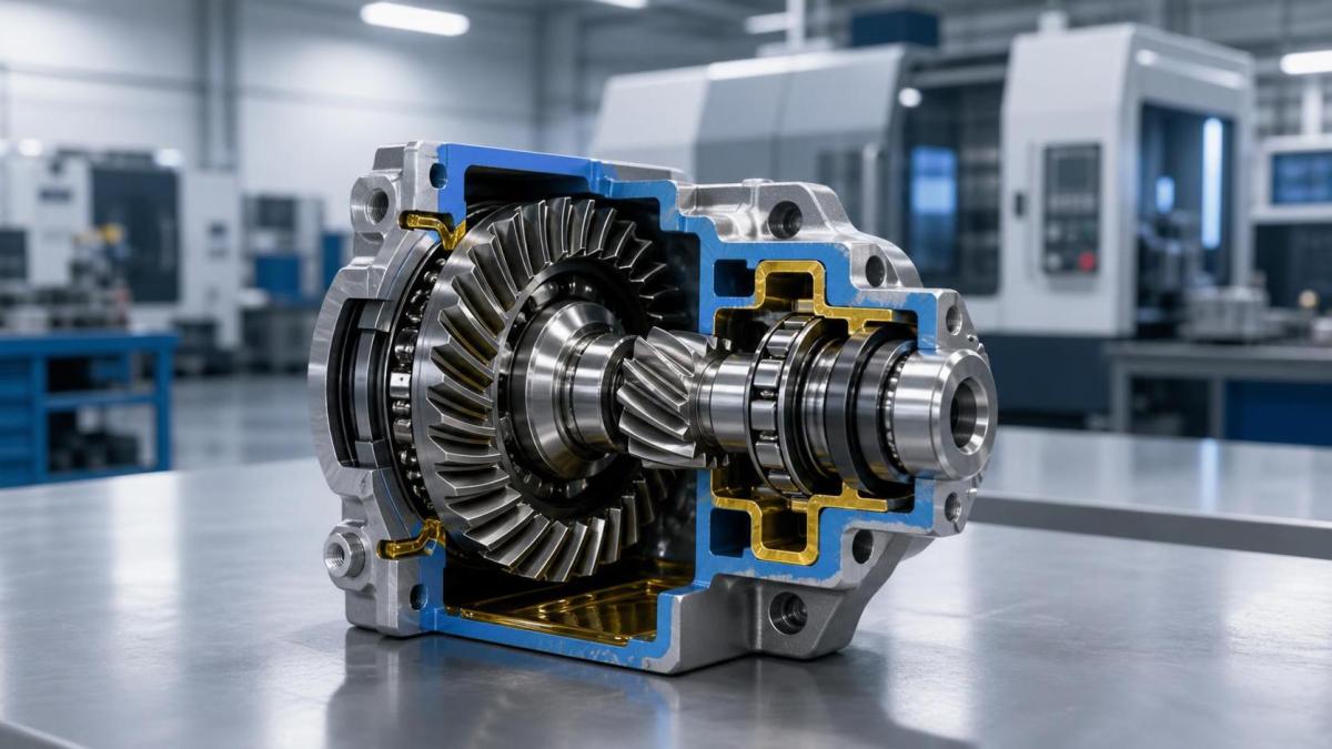
The Engineering Checks That Should Happen Before a Design Is Frozen
Project schedules often encourage teams to move quickly from concept to detailed drawings. With internal bevel gear applications, a short design-for-manufacture review before tooling or procurement is released can prevent expensive rework. The following checks are especially important.
Torque is only the starting point
Rated torque helps establish tooth size and material requirements, but it does not tell the full story. A project manager should ensure that the design team has considered peak torque, reversal frequency, shock loading, start-stop duty, and the consequences of a stalled driven load. Compact drives frequently see high transient loads because the system has little inertia or because the driven mechanism changes direction rapidly.
Tooth-root strength, surface contact stress, and shaft or housing deflection should be evaluated as one system. A gear pair may appear adequate in isolation but lose contact quality once the housing expands under temperature or the bearing seats deflect under load.
Contact pattern and mounting sensitivity
Bevel gear meshes are highly sensitive to relative position. Small changes in mounting distance, shaft angle, bearing play, or housing stiffness can shift the contact pattern toward an edge of the tooth. In an internal configuration, inspection access may be less convenient, making it even more important to establish the correct datums and tolerance chain early.
Specify functional references, not only individual dimensions. The supplier and assembly team need to understand which bore, shoulder, flange face, or bearing seat governs the gear’s final position. A drawing with tight tolerances but unclear functional datums can still produce inconsistent assemblies.
Material and heat treatment must suit the process route
Gear performance is shaped by material cleanliness, fiber flow, heat-treatment response, and finishing method. For loaded right-angle drives, the desired hardness profile and core toughness must align with the anticipated duty cycle. At the same time, the chosen route must account for distortion. A component that is difficult to fixture after heat treatment may require additional stock allowance or a different finishing strategy.
Precision forging can be particularly useful when the blank geometry is complex and material utilization matters. Liaocheng Jiucheng Auto Parts Co., Ltd. develops forged and machined gear-related components for automotive, wind-power gearbox, mechanical, and marine applications. Its precision-forging and machining capability is relevant when a project needs a controlled blank form before gear cutting, finishing, and final inspection. For a project manager, the practical value lies in involving the manufacturing team early enough to discuss draft, fillet radii, machining allowance, datum locations, and grain-flow direction.
Think about the whole bearing-and-seal system
An internal bevel gear does not operate alone. Axial thrust from the mesh must be absorbed by suitable bearings, and the bearing arrangement influences shaft stiffness and backlash stability. Seal selection must accommodate rotational speed, lubricant type, pressure variation, and shaft movement. In compact housings, these components compete for the same space.
A common mistake is to optimize the gear envelope first and treat bearings as a later packaging task. In reality, a slightly different gear geometry may permit a more stable bearing span, and that change can improve tooth contact, noise, and durability simultaneously.
Manufacturing Choices That Change the Business Case
When project budgets are reviewed, the focus often lands on the finished unit price. That is understandable, but the production route deserves equal attention. A heavily machined blank can be viable for prototypes or low-volume specialized equipment. As volumes rise, the cost of material removal, chip handling, cycle time, and tool wear becomes more visible.
Near-net precision forging can reduce the amount of stock that must be removed before final machining. It may also support better material use compared with traditional routes, especially for parts with hubs, flanges, irregular cross-sections, or integrated structural forms. The economic case is strongest when the geometry is stable, annual demand justifies tooling consideration, and the final design has been reviewed for forgeability rather than copied directly from a machined-from-solid concept.
Still, forging is not automatically the answer to every requirement. Internal tooth access, highly specialized tooth forms, low production quantities, or frequent engineering changes may favor alternative blank strategies. The right question is not “Can this be forged?” but “Which manufacturing route gives the required quality, schedule flexibility, and total cost for this program?”
A Practical Specification Brief for Project Managers
When requesting a feasibility review or supplier quotation for an internal bevel gear, provide more than a nominal module and outside diameter. A useful package includes the transmission ratio, shaft angle, expected torque spectrum, speed range, target backlash, duty cycle, lubrication method, operating temperature, noise expectations, material preference, heat-treatment requirement, and available envelope.
It should also identify the interfaces that cannot move: bearing locations, housing datum faces, mating shaft dimensions, mounting flanges, and assembly direction. If the gear is part of a larger reducer, share a sectional layout rather than supplying only the isolated component drawing. That context allows the supplier to identify collisions, tooling limitations, and inspection constraints before they become schedule problems.
For high-consequence programs, agree on the validation path as well. This may include dimensional inspection, tooth-profile verification, runout measurement, hardness checks, metallographic review where appropriate, and contact-pattern evaluation during assembly. The exact plan will vary by application, but the acceptance method should not be left until the first production batch arrives.
Common Shortcuts That Create Trouble Later
- Assuming a compact envelope automatically reduces cost. Smaller packaging can increase tooling complexity, machining difficulty, or assembly sensitivity.
- Copying external bevel gear tolerances into an internal configuration. The functional datums, access limitations, and inspection approach may be different.
- Ignoring heat-treatment movement. A well-machined pre-heat-treatment part can still miss final contact requirements if distortion is not planned for.
- Separating gear design from housing design. Housing stiffness and bearing-seat accuracy directly affect mesh behavior.
- Requesting a quote without a duty profile. A supplier can price a part, but cannot responsibly assess load-related risk from dimensions alone.
Making the Right-Angle Drive Work as a System
The best internal bevel gear solution is rarely the one with the most unusual geometry. It is the one that fits the equipment’s available space, transmits the real load reliably, can be manufactured with controlled variation, and remains practical to assemble and maintain. For project managers, that means bringing gear engineering, forging strategy, machining capability, quality planning, and housing design into the same conversation.
When those decisions are made early, an internal bevel gear can become a useful architectural tool for compact right-angle drives rather than a late-stage complication. The result is a more deliberate path from concept layout to production-ready transmission—one in which space efficiency is supported by manufacturability, not purchased at its expense.
Please give us a message