



Related Posts
Online Message
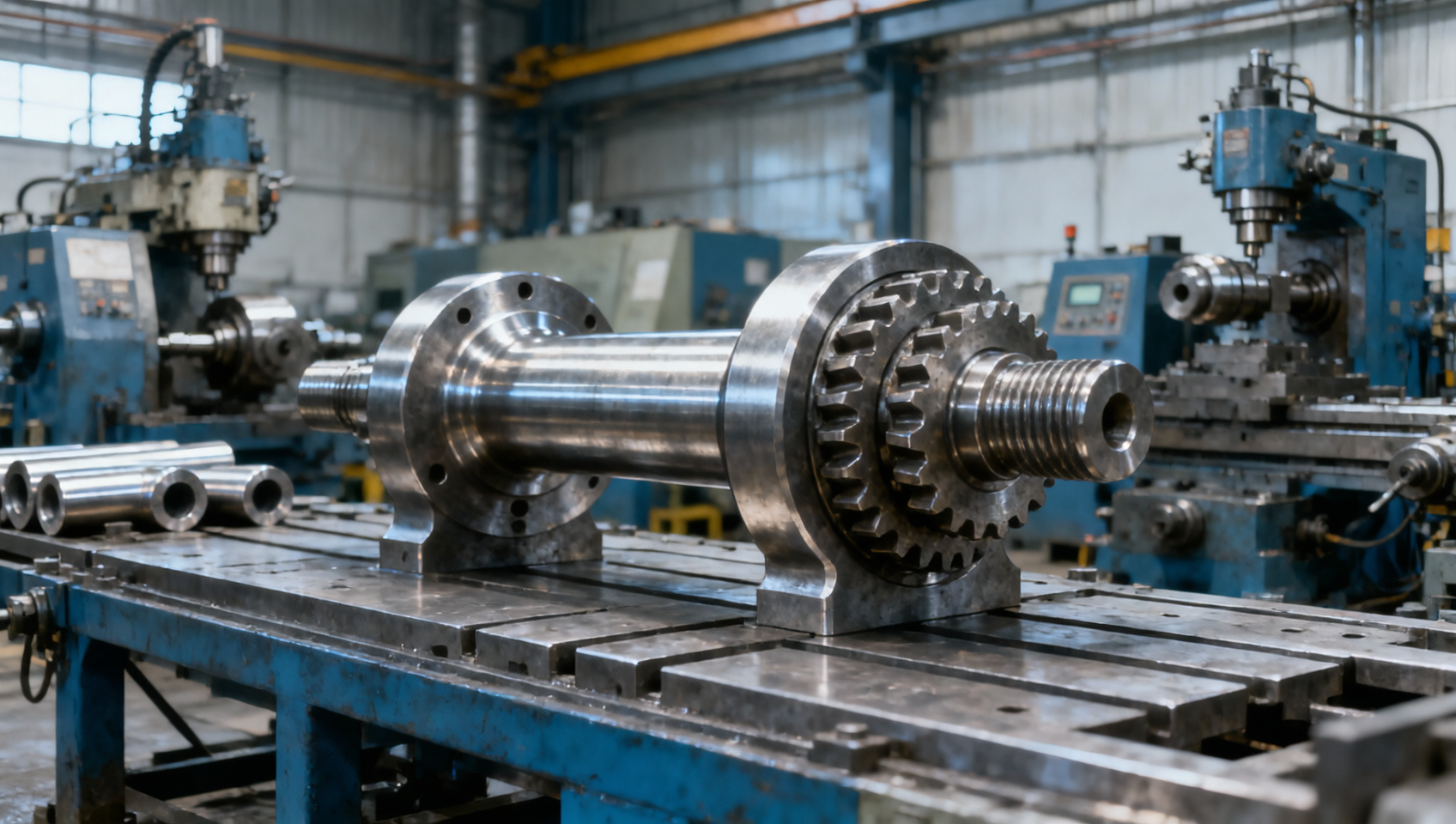
A shaft blank for a crusher drive, marine transmission, wind gearbox, or heavy industrial pump may look straightforward on a drawing: a round section, shoulders, splines, keyways, and perhaps a gear seat. Yet the choice between a cut length of bar stock and a forging can determine where fatigue cracks begin, how much machining is required, and how confidently the part carries repeated torque. For heavy-duty rotating equipment, round forgings usually outperform bar stock when the component has high cyclic loads, changing diameters, critical fillets, or a failure consequence that is difficult to tolerate.
Bar stock remains practical for simple, lightly stressed parts and prototypes. It is readily available, dimensionally predictable, and often economical when little material must be removed. The advantage shifts toward a forged round when the final geometry needs material continuity around journals, flange transitions, gear seats, or other locations where load paths turn. The decision is not “forging is always better”; it is a question of matching the starting form to the service conditions and finished shape.
The operating situation that exposes the difference
Rotating equipment rarely applies a perfectly steady load. A transmission shaft can see torque reversals during starting and stopping. A gearbox input may experience torsional pulses from a motor or engine. A large pinion shaft can combine torsion with bending from gear mesh forces. In these applications, the highest stress is often concentrated at a diameter change, a shoulder radius, a spline root, a keyway, or the edge of a pressed-on component.
With bar stock, the internal grain direction generally runs along the length of the bar. Once a complex profile is machined from it, those longitudinal fibers may be cut across at shoulders and contours. A round forging can be designed so that grain flow follows the external form more closely, especially around stepped diameters and flange-like transitions. This does not eliminate the need for proper material selection, heat treatment, machining control, and inspection. It does, however, provide a more favorable starting structure for parts that repeatedly transmit power.
The difference becomes visible in the planning stage. When an engineer sees that a large amount of stock will be turned away from a bar to create a stepped shaft or hub, that is often a signal to evaluate a forged blank. The question is not merely how much metal will be removed. It is whether the machining process is removing material from areas that must later resist the highest cyclic stresses.
Where round forgings have the clearest advantage
Stepped shafts with loaded shoulders
A shaft with several bearing journals, gear seats, and a coupling end is one of the most common candidates. The transition from a large diameter to a smaller journal is a natural stress raiser, even when the drawing includes a generous fillet. Under combined bending and torsion, this region may become the limiting point for fatigue life.
A forged preform can place material where each diameter is needed before final machining. The outer contour is closer to the finished profile, and the grain flow can wrap through the shoulder area instead of being extensively severed by turning. This is especially useful where the shoulder is not merely a dimensional feature but a load transfer zone between a gear, bearing, or coupling and the shaft body.
Gear blanks and integral gear-shaft parts
Gear components are often judged primarily by tooth accuracy, but the blank beneath the teeth matters just as much. Torque moves from the teeth through the rim, web, hub, and bore or shaft interface. Where a gear is integral with a shaft, the material must handle the transition from one geometry to another without creating a weak section beneath the finished teeth.
A round forging is often a better starting point for pinion shafts, gear hubs, and forged gear blanks with substantial hub-to-rim transitions. It may also be suitable where the part will be machined into a Bevel gear blank, particularly when the hub, bore, and tooth-bearing region must carry repeated torque and directional loading. The final decision still depends on gear design, module, heat-treatment route, and machining allowance, but the blank form should be considered early rather than after the gear geometry is fixed.
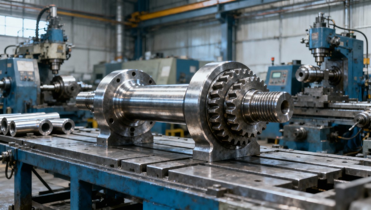
Flanged, shouldered, and hubbed rotating parts
Some rotating components have a compact central body with a projecting flange, collar, or hub. Examples include coupling hubs, rotor supports, large flanged shaft ends, and certain marine drive parts. Producing these shapes from bar stock can mean removing a large volume of material around the flange or leaving abrupt transitions that demand careful machining.
Forging is useful here because the preform can be upset or shaped to create the wider section without relying on extensive removal of sound material. In addition to reducing waste, this can support a better material flow pattern through the hub and transition zones. The value is greatest where the flange transfers torque, clamps another component, or experiences alternating bending loads.
Large diameters with meaningful machining allowance
As component diameter and finished complexity increase, the efficiency of machining from bar stock can decline quickly. A simple bar may have to start significantly larger than the finished body in order to retain enough material for an enlarged section elsewhere. The result is long turning cycles, more chips, more handling, and greater exposure to distortion after material removal.
Round forgings reduce this gap by supplying a near-net outside shape with controlled allowance for finish machining. They are not necessarily the best choice for every large part; very low volumes, unusual alloy availability, or highly simple geometry can favor bar. But when a heavy component has multiple diameter steps or an enlarged hub, the material and machining implications deserve a side-by-side comparison.
Why grain flow matters, and what it does not guarantee
The term “grain flow” is sometimes used too loosely. In a forged component, plastic deformation during forging elongates and redirects the material structure. When the forging sequence and die design suit the part, that flow can follow the outer contours that later carry service stresses. For a round forged shaft, the goal is not cosmetic appearance; it is a sound internal and external structure aligned with the part’s intended form.
This can be advantageous under fatigue loading because cracks often initiate at local stress concentrations. A favorable forged structure may provide better resistance to crack initiation and propagation than a heavily machined profile cut from a straight bar, assuming comparable chemistry, cleanliness, heat treatment, and process quality.
However, a forging cannot compensate for poor design choices. A very sharp shoulder, undersized fillet, inadequate case depth, incorrectly specified hardness, or poorly finished spline root can still dominate component performance. Nor does every forged blank automatically have ideal properties. Engineers should define material grade, reduction requirements where relevant, heat-treatment condition, machining allowance, and inspection expectations based on the part’s service demands.
A practical comparison before selecting the blank
The most useful comparison is made from the finished part drawing, not from a general preference for one supply form. Start by marking the surfaces that transmit load and the locations most likely to see stress concentration. Then compare how the two starting forms affect those regions.
This comparison should include the whole manufacturing route. A lower price per kilogram for bar stock can be misleading when it requires a much larger starting diameter, produces high chip volume, extends machining time, and creates more opportunities for distortion. Conversely, a forging can be uneconomical when the part is a plain cylindrical pin, the order quantity is very small, or the die cost cannot be distributed across enough pieces.
Do not compare only the outside shape
A common mistake is to look at a forged blank and ask whether it will reduce machining time, without checking the locations of final load-bearing features. The bore, keyway, spline, tooth root, and heat-treated surface may matter more than the outer diameter. For example, an integral gear shaft can have a well-shaped forged exterior but still require close control of the bore concentricity and gear-seat runout. The forging choice improves the starting condition; it does not reduce the precision required later.
Another mistake is to assume that all round forgings should have minimal allowance. Allowance must be sufficient for scale removal, decarburization cleanup where applicable, geometric correction, and final surface finish. Too little allowance can expose surface conditions that machining was intended to remove. Too much allowance defeats part of the forging’s material-saving and cycle-time benefit. The correct amount depends on size, alloy, forging method, heat-treatment sequence, and the tolerances of the finished part.
Questions to resolve with the drawing in hand
Before specifying round forgings, it helps to clarify a few issues that directly affect both performance and manufacturability:
- Which sections carry the highest torque, bending moment, or contact load?
- Are there abrupt diameter changes, narrow fillets, spline roots, or keyways near those sections?
- Will the part be through-hardened, induction hardened, carburized, nitrided, or left in a normalized or quenched-and-tempered condition?
- What machining operations remain after forging, and what allowance does each operation require?
- Is concentricity between journals, gear seats, and bores critical to vibration or mesh quality?
- Will the equipment experience frequent starts, reversals, overload events, or sustained high-speed operation?
- What inspection methods are appropriate for the component’s size and service consequence?
These questions often reveal whether the part is truly a simple machined cylinder or a fatigue-sensitive transmission component disguised as one. A forged blank is more likely to be justified when several answers point toward cyclic loading, section transitions, substantial material removal, and high cost of unplanned downtime.
Process details that preserve the advantage
The benefit of a forging can be reduced by weak control after forging. Proper normalization, quenching and tempering, or other specified heat treatment is needed to achieve the intended balance of strength, toughness, and machinability. Turning practices should protect shoulder radii and avoid surface damage at fatigue-sensitive locations. Where grinding is used, burn control and surface integrity are important because a fine dimensional finish does not automatically mean a sound fatigue surface.
For rotating parts, dimensional relationships also deserve attention. Runout between bearing journals and gear seats can affect vibration, contact pattern, and bearing behavior. When the component includes teeth, splines, or a coupling interface, datum selection should be planned across forging, rough machining, heat treatment, and finish machining. Treating each operation as isolated can create tolerance accumulation that is difficult to correct at the end.
A forging supplier should therefore receive more than an overall length and maximum diameter. Useful information includes the finished drawing, material specification, required heat-treatment condition, machining datum strategy, critical zones, inspection requirements, and expected production volume. Clear input allows the blank shape and allowance to be developed around the real functional needs of the part rather than around a generic round profile.
Questions that often arise during early selection
Can bar stock provide adequate performance for a heavy-duty shaft?
Yes. Bar stock can be entirely appropriate when the shaft geometry is simple, the material grade and heat treatment are suitable, and fatigue loading is within the design margin. The case for a round forging becomes stronger when the shaft has major steps, loaded shoulders, or demanding cyclic service.
Does a forged blank remove the need for nondestructive testing?
No. Inspection requirements should reflect the part’s material, size, service condition, and failure consequence. Forging improves the starting form but does not replace the need for suitable dimensional checks, material verification, or inspection methods where they are specified.
Are round forgings only for large production runs?
Not always. Stable repeat production generally improves the economics because tooling and process development can be shared across more parts. Still, a lower-volume part may justify forging when the component is large, expensive to machine from bar, or especially sensitive to fatigue performance.
Please give us a message