



Related Posts
Online Message
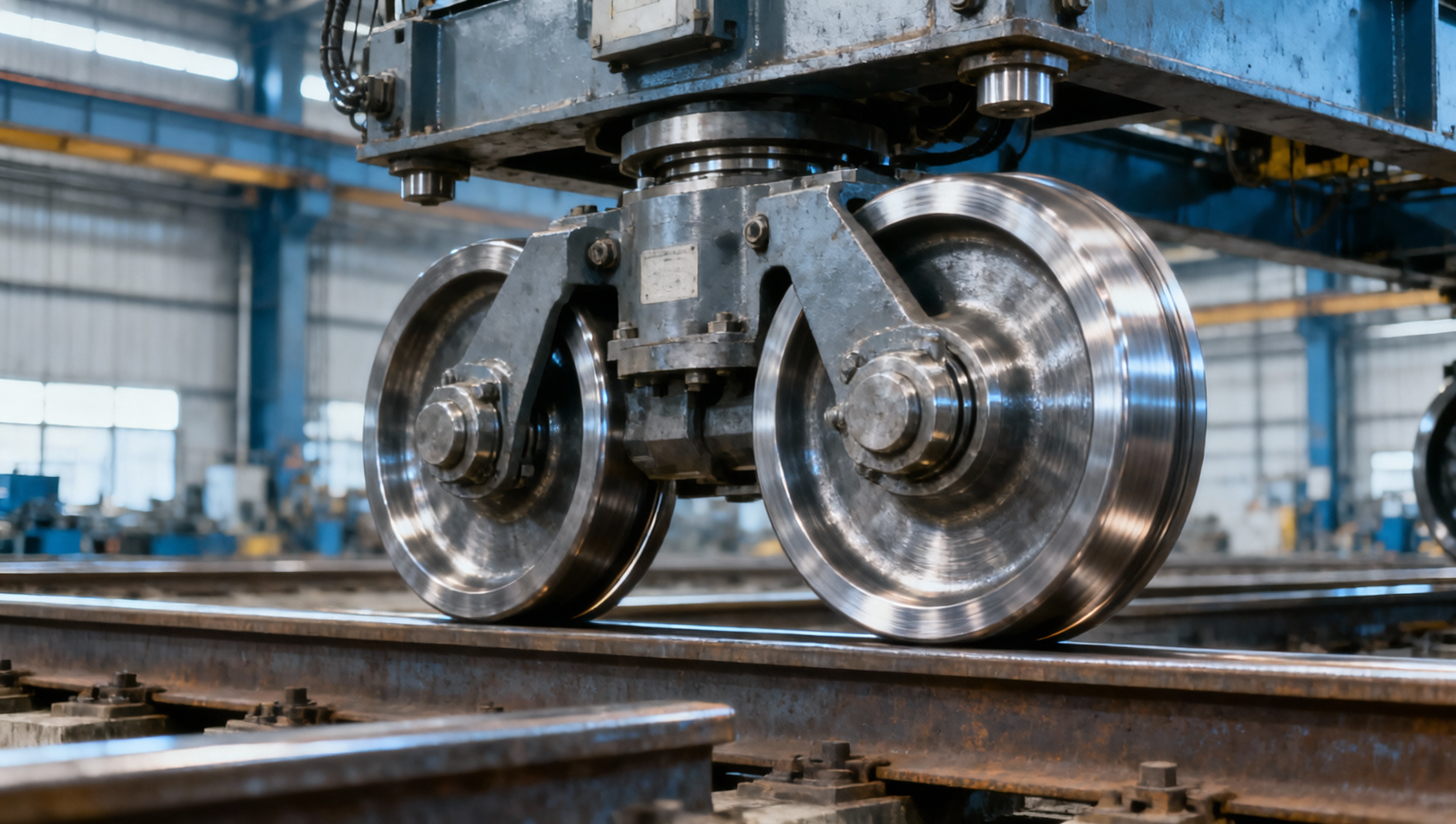
Choose double flange bridge crane wheels when the crane’s guidance arrangement requires a flange on each side of the rail head, and the rail geometry, wheel spacing, and lateral clearances have been verified together. During a replacement assessment, recurring flange wear or travel binding may suggest that more guidance is needed. However, adding a second flange without identifying the cause can increase rubbing, drive load, and rail damage rather than improve travel.
The strongest justification is an engineered wheel-and-rail arrangement that needs bilateral guidance while allowing normal running clearance. Single-flange wheels or separate guide rollers may be more suitable where guidance is provided elsewhere. Neither wheel type corrects runway misalignment, unequal effective rolling diameters, or unsynchronized drives; those faults require attention before a wheel change is approved.
Start with the guidance arrangement, not the flange count
A double-flange wheel has a flange on both sides of its tread. The tread carries the vertical load on the rail head, while the flanges limit lateral displacement when the available clearance is taken up. Flange contact generates lateral forces that must be supported by the wheel, axle, bearings, end carriage, rail, and runway structure.
This does not mean both flanges should continuously touch the rail. Persistent contact, especially alternating hard contact during travel, indicates a condition requiring investigation. A wheel can have two flanges and still operate with clearance between its flange faces and the rail sides.
Assess the complete wheel arrangement across both end carriages. Determine which wheels provide lateral guidance, whether guide rollers are installed, and whether the design permits movement needed to accommodate track and structural tolerances. Adding flanges at every wheel position can overconstrain a system intended to use a different guidance strategy.
A flange is also not a complete derailment-prevention system. Wheel unloading, rail discontinuities, unsuitable flange profiles, and excessive lateral forces remain relevant. Any requirement for retention or anti-derailment devices must be evaluated separately under the crane’s applicable design basis.
Situations that justify considering a double-flange design
For a new crane or a documented replacement, the following conditions support evaluation rather than automatic approval:
- The approved design uses wheel flanges for guidance on both sides of the rail. The proposed profile matches the intended wheel positions and the actual rail section.
- Lateral loading can act in either direction. The engineering assessment establishes the required guidance forces and confirms that the supporting components can carry them.
- The runway geometry is controlled. Rail alignment, gauge variation, elevation, and joint condition are compatible with the proposed clearance envelope.
- The duty includes frequent travel or direction changes. Flange strength, wear allowance, and contact behavior have been evaluated for the operating cycle rather than only for static load.
Heavy service alone is not a reason to select two flanges. A higher vertical wheel load increases the importance of tread contact stress, wheel diameter, material properties, and rail capacity. It does not establish how lateral guidance should be provided.
Likewise, replacing a worn double-flange wheel with the same nominal type is reasonable only after confirming why it wore. Normal service wear and damage caused by skew demand different responses. The original drawing is a useful starting point, but it should be checked against the installed rail and any subsequent modifications.
Rail fit determines whether extra guidance becomes extra friction
The decisive fit dimension is the relationship between the rail head and the wheel’s internal flange spacing. Nominal rail width is insufficient: rail-head shape, corner radii, wear, and local deformation affect where contact occurs. The tread profile and flange-root radius must allow the intended tread contact without unintended interference at the rail corners.
Review the cross-section using the actual wheel and rail drawings, then examine the tolerance stack over the full runway. One correctly fitted wheel at one location does not demonstrate that all wheels can travel freely through variations in rail gauge, end-carriage geometry, and track alignment.
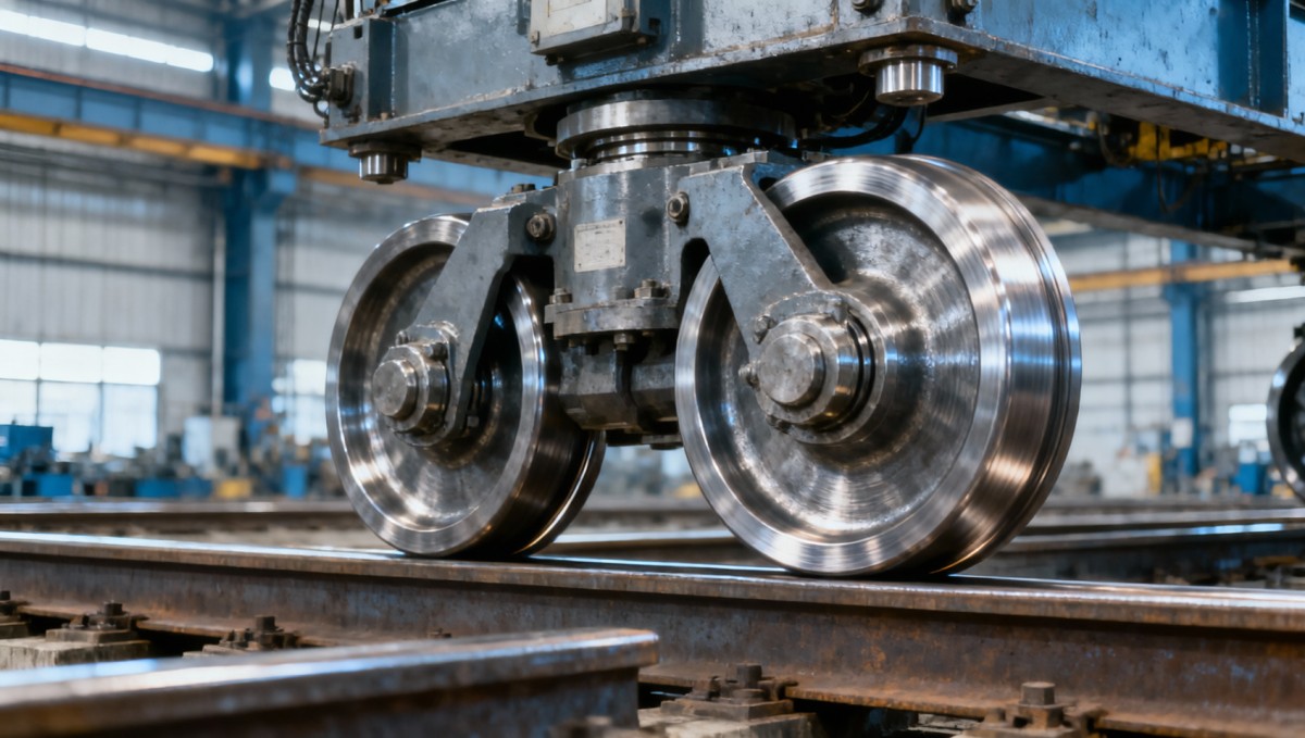
There is no universal flange-clearance value suitable for every bridge crane. Too little clearance can produce persistent rubbing or binding; too much may allow excessive lateral movement before guidance engages. The acceptable range depends on wheel profile, rail geometry, crane span, structural movement, and the design requirements.
Investigate skew before changing the wheel specification
A bridge that tends to lead on one side can push its wheel flanges against the rails. Installing a more restrictive profile may conceal lateral movement while increasing the force needed to travel. The investigation should separate track-related effects from faults that follow the crane along the runway.
- Map the symptoms. Record where rubbing, noise, vibration, or elevated drive current occurs, including travel direction and load condition. Location-specific symptoms warrant close inspection of the runway.
- Survey the track. Check rail straightness, gauge, elevation, joint steps, fastening condition, and local damage against the approved requirements.
- Inspect wheel geometry. Measure tread wear, effective rolling diameter, flange wear, axle alignment, and wheel squareness. Unequal effective diameters can contribute to unequal travel even when nominal wheel sizes match.
- Check the drive system. Review motor coordination, brake release, gearbox condition, coupling alignment, shaft connections, and bearing drag where relevant.
Drive-component replacement should remain distinct from flange selection. Where a mechanically linked drive includes a transmission shaft, a Drive Shaft supplier may be relevant to a separate sourcing task. Shaft interfaces and operating requirements still need verification; changing a shaft does not resolve incompatible wheel-and-rail geometry.
Shiny flange faces, burrs, or rail-side wear are evidence of contact, not proof that a second flange is needed. Their position and pattern help identify the cause. Extensive wear on several wheels calls for a system-level review rather than isolated wheel replacement.
Specify load capacity, material, and machining as one package
Once the guidance arrangement is justified, the wheel needs a complete mechanical specification. Start with the design wheel loads, including relevant dynamic effects and unequal load distribution. Do not simply divide the crane’s total weight and rated load by the number of wheels: trolley position and structural behavior can change individual reactions.
The wheel diameter, effective tread contact width, rail-head geometry, and material pairing determine the contact-stress assessment. Lateral loading also requires evaluation of the flange and its root, together with the axle and bearing arrangement. A stronger flange is of limited value if another component becomes the weak point.
Forging and heat treatment
A forged blank can be a suitable starting point, but “forged steel” is not an adequate purchase specification. Identify the steel grade, required mechanical properties, heat-treatment route, and inspection requirements. The forging process must produce sound material with sufficient machining allowance, particularly around the hub, tread, and flange roots.
Hardness should be specified with its measurement location and acceptance range. Where surface hardening is required, define the hardened region and depth requirement as well. Increasing hardness without considering toughness, the rail material, and service conditions can exchange wear resistance for cracking risk or accelerated rail wear.
Finished geometry
The drawing should control tread diameter and profile, flange dimensions, root radii, bore or hub interfaces, and relevant runout. Concentricity between the running surface and mounting features affects smooth rotation. Wheel matching requirements also matter where multiple driven wheels must maintain compatible rolling behavior.
Inspection records should correspond to the supplied components. Material traceability, heat-treatment records, dimensional results, hardness measurements, and specified nondestructive examinations provide a stronger acceptance basis than a general statement that the wheel is suitable for crane service.
When single-flange wheels or separate guides deserve priority
Single-flange wheels can be appropriate when their orientation and placement provide the guidance required by the crane design. A second flange is unnecessary if it adds constraint without serving a defined lateral-load path. The comparison therefore belongs at the system level, not between two isolated wheel photographs.
Separate guide rollers may be considered where the design separates vertical load support from lateral guidance. This can offer different adjustment and maintenance options, but it introduces its own contact forces, mounting requirements, and wear points. It is not automatically a lower-maintenance alternative.
Do not convert between these arrangements solely by changing the wheel profile. Wheel spacing, axle position, end-carriage geometry, guide locations, and lateral clearances may need revision. The change can also alter forces transmitted into the runway.
Where track distortion or drive mismatch is unresolved, retain the selection decision as pending. Repairing the underlying condition may show that the existing guidance concept was suitable and that the replacement should preserve it.
Define the evidence needed before release
A useful supplier request includes the rail section and measured condition, wheel-position drawing, mounting dimensions, vertical and lateral design loads, travel speed, operating duty, and environmental conditions. For replacements, include wear measurements and identify any differences between the original drawing and the installed equipment.
Ask for a proposed wheel drawing and inspection plan that make acceptance criteria explicit. Any substituted material, altered flange spacing, revised heat treatment, or changed mounting interface should receive engineering approval before manufacture.
Commissioning must verify the assembled arrangement, not just the wheel dimensions. Under an approved procedure, confirm clearances and inspect travel through the runway, progressing through operating conditions as authorized. Pay attention to flange contact patterns, abnormal noise, drive behavior, and local binding. These checks cannot replace the design calculation, but they can reveal installation problems.
Approve double-flange wheels only when bilateral guidance has a defined purpose, the tolerance stack permits travel, and the complete load path is adequate. If approval depends on the extra flange forcing a misaligned crane to run straight, the problem remains unresolved.
Please give us a message