



Related Posts
Online Message
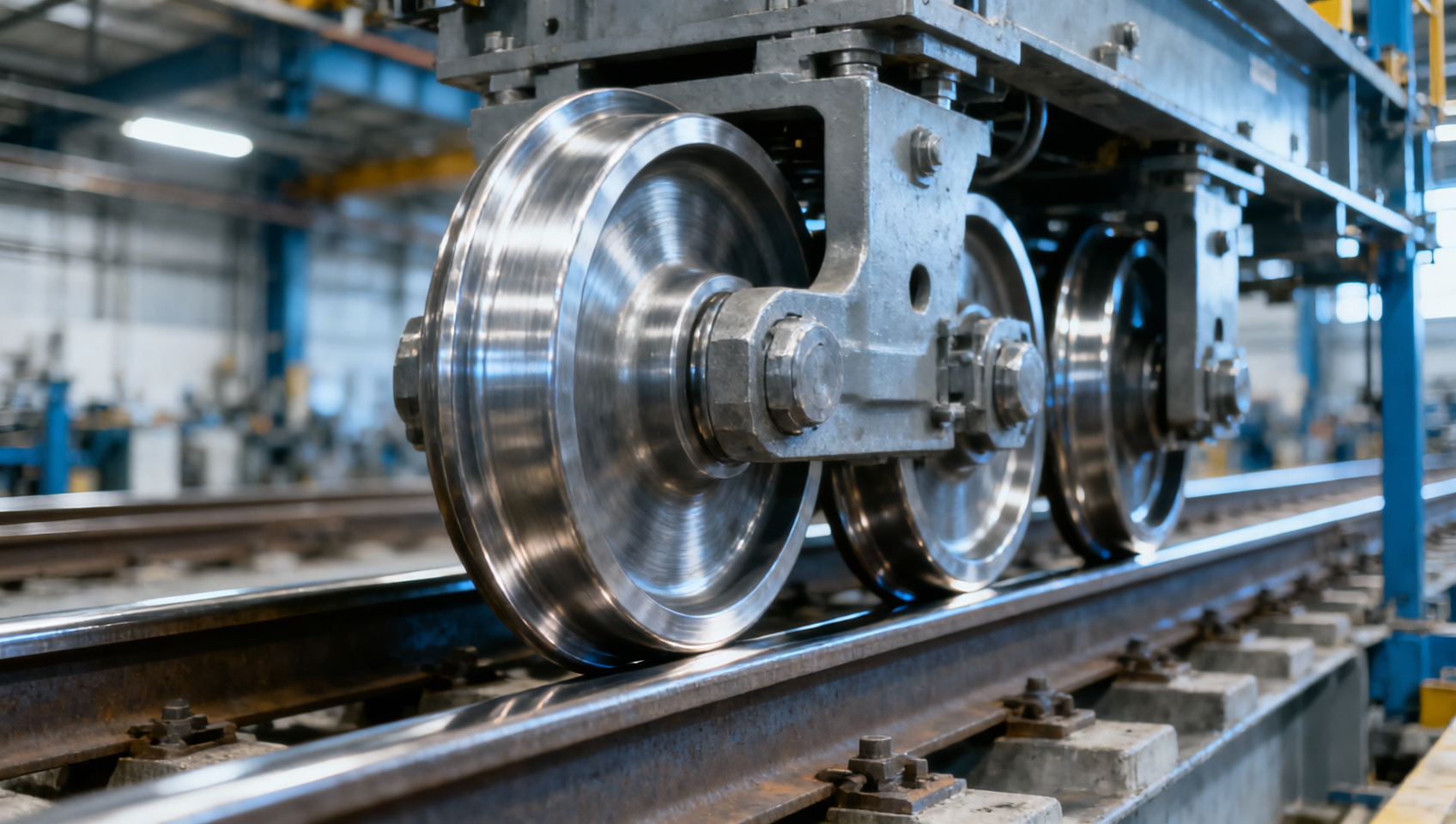
How rail head width affects double flange gantry wheel selection
Rail head width is a critical starting point when evaluating double flange gantry wheels, but matching nominal dimensions alone does not ensure reliable operation. The clearance between the rail head and wheel flanges must be considered alongside tread geometry, rail tolerances, alignment, and operating loads. Insufficient clearance can increase flange contact and wear, while excessive clearance may allow unwanted lateral movement.
The practical question is not simply, “Will this wheel fit over the rail?” It is, “Will the wheel remain compatible with the entire runway when the gantry is loaded, accelerating, reversing, and travelling through joints?” That distinction should be settled before machining or procurement, not during commissioning.
Start with the rail profile, not just its catalogue width
Rail head width describes the transverse width of the rail’s upper section. For selection purposes, however, one number does not fully describe the wheel–rail interface. Head curvature, corner radii, side slopes, and the rail’s installed condition determine where the tread carries load and where a flange could make contact.
Two rails with similar nominal head widths may therefore require different wheel profiles. A flat running surface and a crowned rail head do not necessarily produce the same contact pattern. Likewise, the distance between the flange faces may change with height if those faces are tapered. A dimension taken near the flange tips can be misleading if the rail head sits closer to the flange roots in service.
For an existing installation, obtain the rail section drawing and measure representative locations along both runway rails. Include joints, visibly worn areas, repaired sections, and transitions between old and replacement rail. Check for side wear and mushrooming rather than assuming that years of operation have only made the head narrower.
On a new runway, use the specified rail profile and its permitted dimensional variation. A nominal rail designation is useful for identifying the section; it is not a substitute for the tolerances needed to approve a wheel drawing.
Treat flange clearance as a tolerance stack
A useful initial check is the difference between the wheel’s internal flange spacing and the rail head width. Both dimensions must refer to a compatible cross-section and operating position.
Total geometric lateral clearance = internal flange spacing − effective rail head width.
If the wheel is centred and the geometry is symmetrical, the nominal clearance on each side is half that difference. This is a drawing check, not a guarantee of equal running gaps. Rail alignment, wheel positioning, frame deflection, and gantry skew can move the wheel towards one side.
The tightest dimensional condition combines the smallest permitted internal flange spacing with the largest permitted rail head width. The loosest condition combines the largest spacing with the smallest head width. Where flange taper or rail corner geometry changes the available gap, a section overlay is more informative than subtracting two catalogue dimensions.
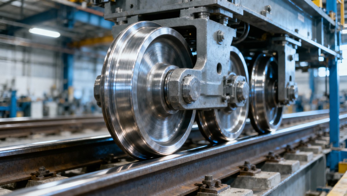
A wheel–rail section drawing should identify the tread, flange working faces, root radii, rail crown, and the reference position used for clearance measurement. Without those references, two suppliers may quote the same “flange spacing” while describing different usable openings.
There is no defensible universal clearance value based on head width alone. The acceptable range depends on the gantry configuration, guidance arrangement, wheel profile, runway condition, and applicable design requirements. Ask the responsible designer to establish that range rather than selecting the smallest gap that appears machinable.
Why a tighter fit can become an expensive mistake
A close fit may look attractive when lateral positioning matters. But double flanges are not a substitute for correcting runway alignment. If the rail spacing varies along the travel path, or the wheel assemblies are not square to the gantry, reducing clearance can turn manageable geometric variation into sustained flange rubbing.
That contact introduces lateral forces and friction into a system intended primarily to roll. Possible consequences include accelerated flange wear, rail-side damage, and additional loading on bearings and wheel mountings. The severity depends on the duty cycle and actual contact forces; occasional guiding contact and continuous heavy rubbing should not be treated as equivalent.
Simply increasing the gap is not always the answer either. Excessive clearance permits more lateral travel before the flange engages. During skewing or direction changes, that can make engagement more abrupt and reduce positional consistency. The objective is controlled guidance with sufficient operating freedom—not zero clearance and not unrestricted movement.
Head width also affects tread support and contact stress
Passing the flange-clearance check does not establish load capacity. The tread must work with the rail’s running surface throughout the permitted lateral movement. The intended contact should remain clear of unsuitable edge or flange-root regions, including when the wheel is displaced towards one side.
A wider rail head does not automatically produce a proportionally larger contact area. Contact depends on wheel diameter, tread shape, rail crown, load, and the elastic properties of both materials. With curved surfaces, the effective contact patch can be much smaller than the apparent overlapping width. Capacity should therefore be checked using the appropriate wheel–rail contact method, not estimated by dividing wheel load by nominal tread area.
Establish the maximum design wheel reaction before evaluating materials or heat treatment. Dividing total gantry weight by the number of wheels can overlook an off-centre payload, unequal support, structural flexibility, and operating effects. Where load sharing is uncertain, the structural and wheel calculations need to be coordinated.
Material selection is a separate decision from dimensional fit. Wheel and rail hardness, toughness, wear behaviour, and the repair strategy should be considered together. Choosing a harder wheel without reviewing the rail can shift wear to the runway rather than resolve the underlying contact problem.
Check the whole gantry before changing one wheel
Replacement work is where nominal matching is especially tempting. An existing wheel may have worn into an apparently generous clearance, while the new wheel returns the assembly to a much tighter condition. Copying the worn wheel’s dimensions can also reproduce damage rather than the original design.
Use the original drawing where available, then compare it with the installed rail and the remaining wheel assemblies. Pay attention to wheel centre spacing, rail gauge, axle alignment, bearing play, and tread diameters. Where driven wheels must run synchronously, diameter differences or drive mismatch can contribute to skewing; changing flange spacing will not correct that cause.
Thermal movement also needs a system-level review. Its effect depends on runway restraints, structural expansion, and temperature differences—not only on the small dimensional change of the rail head itself. An outdoor gantry and a temperature-controlled workshop may need different installation allowances even when their nominal rail sections match.
Be clear about the intended guidance scheme. Where separate guide rollers or other lateral-control components are fitted, confirm how they interact with the wheel flanges. Unintended competing guidance can create contact forces that a simple wheel-width comparison misses.
What a supplier needs to evaluate the interface
A useful enquiry for double flange gantry wheels should include more than an outside diameter and rail designation. The following information allows the supplier and designer to assess compatibility without guessing:
- Rail definition: section drawing, head profile, dimensional tolerances, and measured condition where the runway already exists.
- Wheel geometry: tread diameter and profile, internal flange spacing with its measurement reference, flange height, root radii, bore, and mounting details.
- Operating duty: maximum wheel reactions, travel speed, acceleration, reversals, expected duty cycle, and relevant environmental conditions.
- Installation data: rail gauge and alignment limits, wheel arrangement, guidance method, and any known joint or transition issues.
- Acceptance requirements: material specification, heat-treatment requirements, dimensional inspection, and any testing required by the design or purchase specification.
Separate forged-blank requirements from finished running dimensions. Forging allowances can support efficient production, but the tread profile, flange opening, and bore relationship still need defined final tolerances. Inspection should establish the functional geometry, not merely confirm that the overall width is correct.
Liaocheng Jiucheng Auto Parts Co., Ltd., established in 2015, combines precision forging and mechanical processing for gears, shafts, and related components. Its Bevel gear offering belongs to that broader manufacturing scope. For a gantry-wheel enquiry, however, gear-manufacturing experience alone does not establish wheel–rail suitability: the proposed process, finished geometry, material requirements, and inspection scope still need project-specific confirmation.
Approve a compatible interface, not an isolated dimension
The strongest selection decision connects three checks: clearance across the permitted dimensional range, acceptable tread contact under the design loads, and compatibility with the installed guidance and alignment conditions. A wheel should not be approved solely because its nominal flange opening exceeds the nominal rail head width.
Before releasing machining, request a reviewed wheel–rail section and a documented tolerance assessment. Before commissioning, verify the installed alignment and follow the specified inspection and test procedure. If sustained one-sided flange contact appears, investigate skew, gauge variation, and load distribution before ordering a wider wheel. More clearance can conceal an installation problem without removing its cause.
Please give us a message